
Method and device for detecting viscosity of fluid passing pipe

A technology of measuring devices and measuring methods, applied in the direction of measuring devices, flow characteristics, special data processing applications, etc.

Active Publication Date: 2008-01-23
XIAN DONGFENG MACHINERY & ELECTRONICS
View PDF7 Cites 15 Cited by
  • Summary
  • Abstract
  • Description
  • Claims
  • Application Information

AI Technical Summary

Problems solved by technology

However, when it is implemented on other instruments, many changes may be required to meet the implementation conditions or the instrument itself has the torsion requirements described in the patent, such as Chinese patents 02816604.3 and 02812185.6 or US patent application numbers 11 / 178,431, 10 / 835,471, 10 / 226,242 etc.

Method used


Image

  • Method and device for detecting viscosity of fluid passing pipe
  • Method and device for detecting viscosity of fluid passing pipe
  • Method and device for detecting viscosity of fluid passing pipe

Examples


specific Embodiment

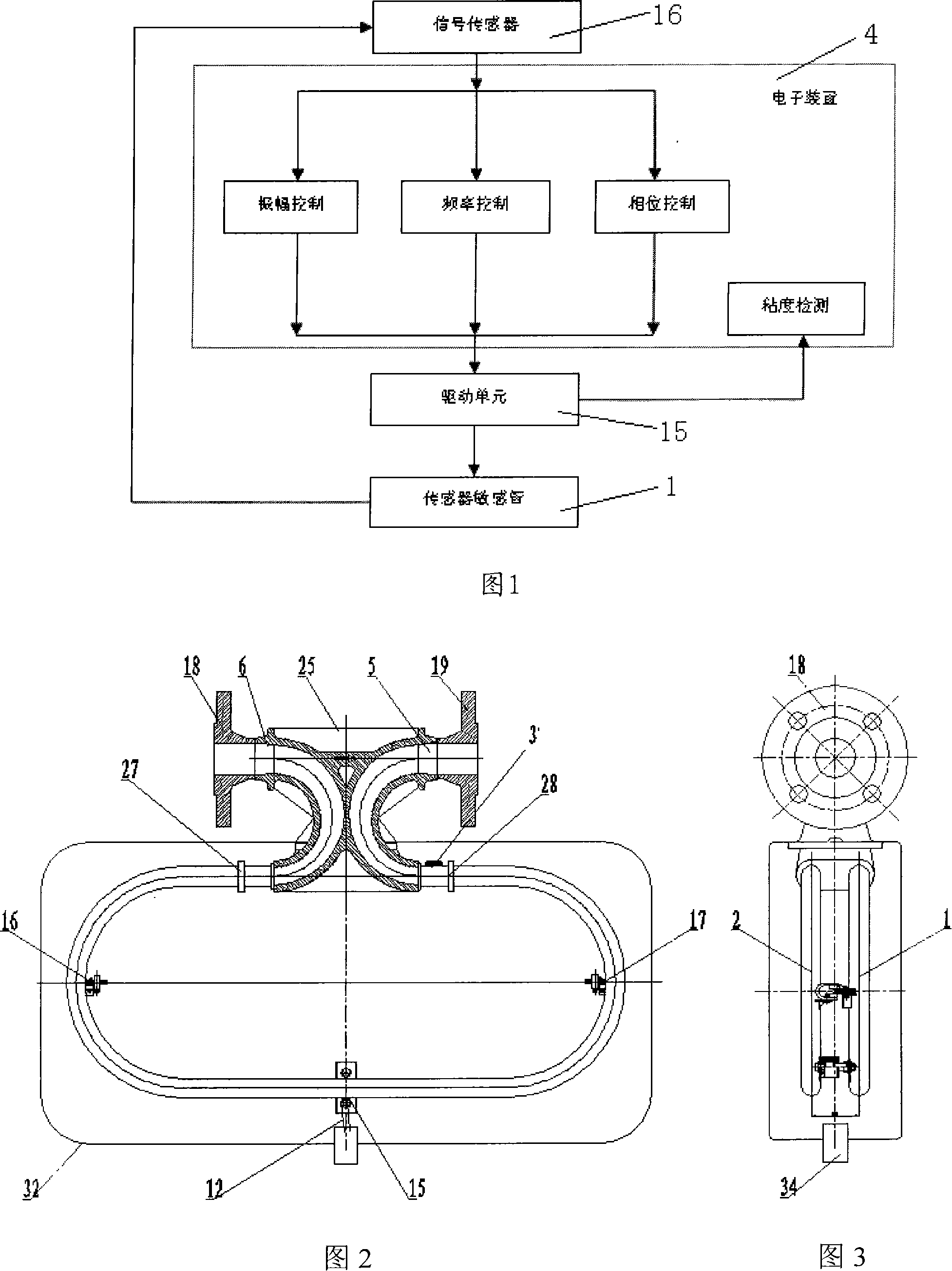
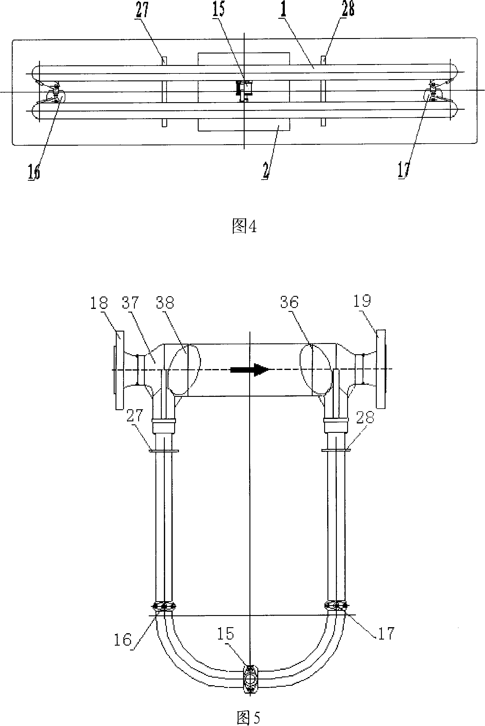
[0054] Referring to Figures 2-4, Figure 2 is a schematic structural view of a double C-type Coriolis mass flowmeter; the present invention can be implemented on this patent 200410073046.2, as shown in Figure 2, it includes two parallel C-type sensitive tubes 1 and 2. The fluid to be measured enters the flowmeter from the main pipe 25 of the main body and is divided into two parts, flows into the sensitive tubes 1 and 2, and then flows into the main body from the outlets of the sensitive tubes 1 and 2 to be combined into one, and is output by the main tube. The mouth 6 flows to the external pipe through the flange 18, and the drive unit 15 is installed in the middle section of the sensitive tube 1 and 2. When working, the two sensitive tubes resonate, and the displacement signal devices 16 and 17 are symmetrically installed in the middle part of the arc of the sensitive tube 1 and 2. , to detect a phase difference signal proportional to Coriolis.

[0055] Fixing plates 27 and 2...


PUM


Abstract

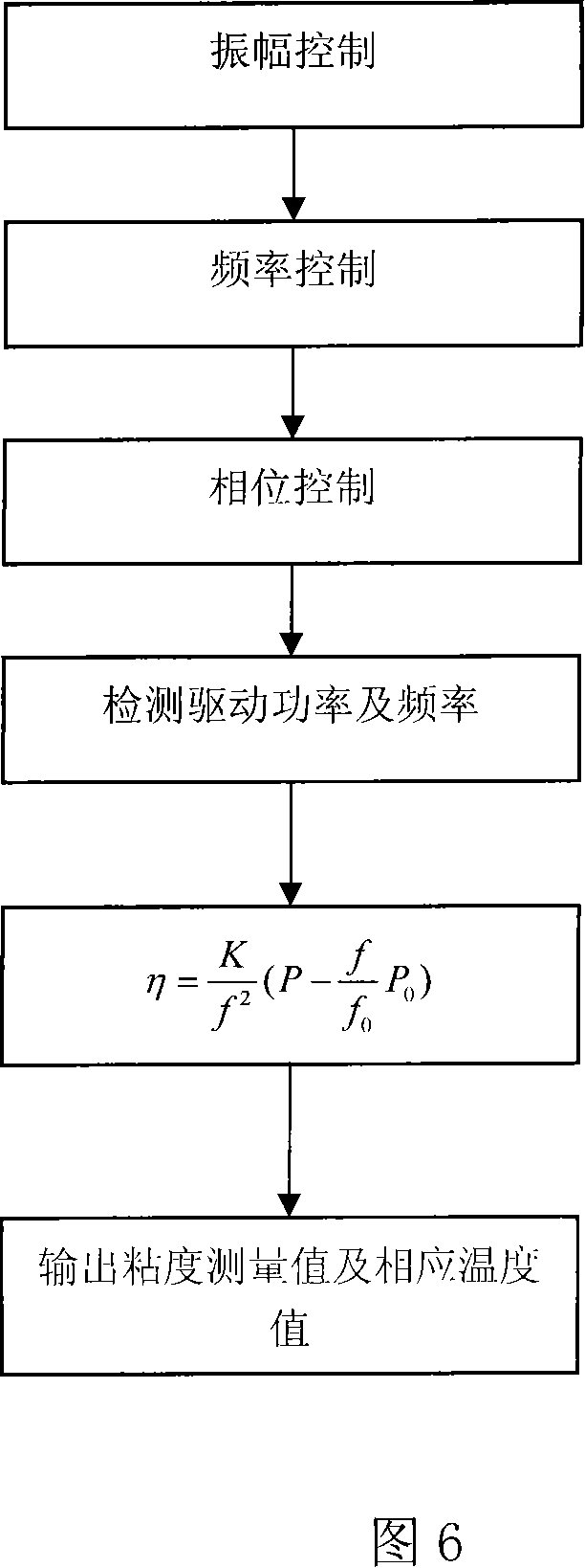
The invention relates to a device and method for testing the viscosity of a fluid passing a pipe. For a prior viscosity tester, for example, American patent 4,524,610, a drive makes a sensor sensitive pipe to generate twisting and vibration, so as to generate frictional force in the fluid; and by measuring the drive current, the dynamic viscosity measurement of the fluid can be obtained, and the dynamic viscosity can be obtained by measuring the fluid density. However, for implementing the patent on other instruments, it needs a lot of changes to meet the implementing condition. The present invention is a device allows to get continuous viscosity value, which can be realized on a Coriolis mass flowmeter and comprises at least a sensor sensitive pipe without changing greatly original device, in addition, by measuring the fluid density, the dynamic viscosity of the fluid can be obtained. The invention is to measure the viscosity of a fluid by making the fluid to reach its optimal harmonic-oscillation point and then taking use of different information at the point. The invention is of simple structure, easy to operate. The method is of simple procedures and accurate test results.

Description

technical field [0001] The invention relates to a device and a method for detecting the viscosity of a fluid passing through a pipeline. technical background [0002] Continuous automatic measurement and control of fluid viscosity is required in many industrial production processes, which is of great significance for improving production efficiency, ensuring product quality, safe production and energy saving. Viscosity measurement is required in the petroleum industry, in transportation using heavy oil as fuel, in the power industry, in various polymerization projects, in paper and textile industry production. [0003] Rotational viscometers and vibratory viscometers in traditional viscosity measuring devices have some common characteristics in the measurement of fluid viscosity: objects will be affected by fluid viscous torque or force to change their original motion. The principle of the rotation method is to determine the viscosity of the fluid by measuring the viscous m...

Claims


Application Information

Patent Timeline
Patent Type & Authority Applications(China)
IPC IPC(8): G01N11/00G06F19/00
Inventor 任建新张鹏周波
Owner XIAN DONGFENG MACHINERY & ELECTRONICS
Learn More