Cooling device

A technology of cooling device and pump device, which is applied in the direction of metal processing machinery parts, maintenance and safety accessories, metal processing equipment, etc., can solve problems such as the adverse effects of temperature adjustment of working machine tools, and achieve improved processing accuracy, economical processing, and reliable functions Effect

Inactive Publication Date: 2010-05-12
HYDAC SYST
View PDF4 Cites 0 Cited by
  • Summary
  • Abstract
  • Description
  • Claims
  • Application Information

AI Technical Summary

Problems solved by technology

The changing mixing in the clean oil tank due to the changing temperature at the outlet of the cooling unit also has a negative effect on the temperature regulation of the machine tool

Method used


Image

  • Cooling device
  • Cooling device
  • Cooling device

Examples


Embodiment Construction

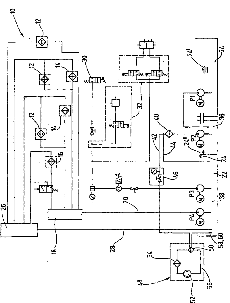
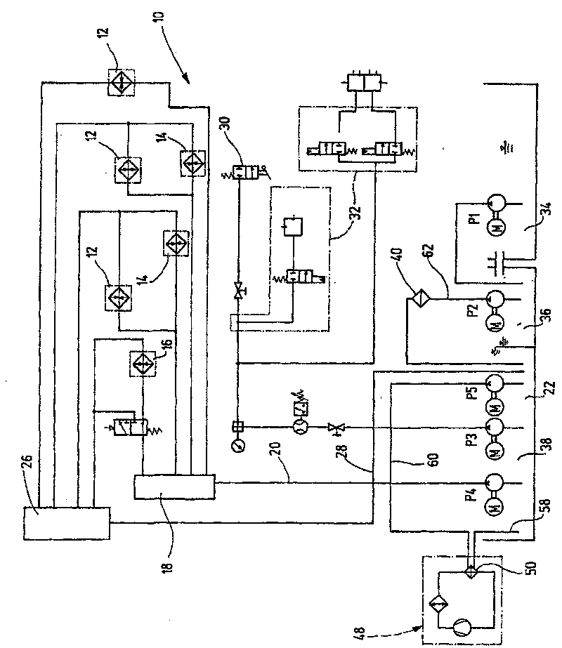
[0021] in the aid of figure 2 Before explaining the cooling device according to the invention in detail, the known structure according to FIG. 1 must first be explained in detail.

[0022] FIG. 1 shows a known cooling device for a machine tool in the form of a grinding machine generally indicated at 10 . The grinding machine 10 has three linear motors 12 as well as two axial motors 14 and a grinding spindle motor 16 for driving a grinding wheel (not shown). The further described motors 12 and 14 enable a five-axis grinding drive by means of which turbine blades or similar components can also be ground with high precision. The motors 12, 14 and 16 are supplied with fluid in the form of cooling lubricant from a clean tank 22 via a distributor 18, via a forward line 20 in the form of a fluid line, by means of a hydraulic pump P4. The possible level of cooling lubricant in the clean oil tank 22 is indicated symbolically by a level indicator 24 . The cooling lubricant delivered ...


PUM


Abstract

The invention relates to a cooling device for a machine tool (10) for cooling a heated fluid, for example a cooling lubricants, comprising at least one refrigerating unit (48) for a fluid which is filtered by a filtering unit (40) and is received form at least one storage tank (38) by means of a pumping unit provided with at least one hydraulic pump (P2), separated clean (22) and waste (36) tanks,wherein the refrigerating unit (48) returns the circulating cooled fluid to the clean tank (22). Since the hydraulic pump (P2) of the pumping unit supplies the fluid only filtered by the filtering unit (40) from the waste tank (36) to the clean tank (22) and another independent hydraulic pump (P5) continues to supply the fluid from the clean tank to the refrigerating unit (48) for a subsequent circulation, the base structure of a known refrigerating device can be preserved and possible pressure losses caused by the blinding of the filter of the filtering unit have no negative effects on the constantly maintained flow rates for the refrigerating unit.

Description

technical field [0001] The invention relates to a cooling device for working machine tools for cooling a heated fluid, such as a cooling lubricant. Background technique [0002] In cooling devices of this known type that have been used in practice, on a working machine such as a grinding machine, the fluid in the form of cooling lubricant discharged into the surrounding environment is collected in a machine bed pool as a collection station and It is delivered by a hydraulic pump to a dirty oil tank that is part of the cooling lubricant storage tank. The dirty and possibly heated fluid carried into the dirty oil tank is conveyed by another hydraulic pump to the filter device, wherein the filtered fluid is thus brought to the filter device via a side branch after passing through the filter device Inside a clean tank of the storage tank, and in a main branch, a portion of the filtered fluid goes to the cooling unit which brings the filtered and cooled fluid in circulation back...

Claims


Application Information

Patent Timeline
Patent Type & Authority Patents(China)
IPC IPC(8): B23Q11/00B23Q11/10B23Q11/12B23Q11/14
CPCB23Q11/146B23Q11/0057B23Q11/1069B23Q11/122Y02P70/10
Inventor R·孔茨W·克莱恩
Owner HYDAC SYST
Why Eureka
Try Eureka