
Optical lens manufacturing and machining system

An optical lens and processing system technology, which is applied to manufacturing tools, metal processing equipment, grinding workpiece supports, etc. Control, improve processing quality, save labor costs

Active Publication Date: 2021-01-26
福源中山光电科技有限公司
View PDF7 Cites 2 Cited by
  • Summary
  • Abstract
  • Description
  • Claims
  • Application Information

AI Technical Summary

Problems solved by technology

[0004] 1) The processing efficiency of manual chamfering is low and the labor cost is high;
[0005] 2) The artificial chamfering method is greatly influenced by human operation, the processing accuracy is not easy to be unified, the processing accuracy and processing quality are greatly differentiated, and the failure rate is increased

Method used


Image

  • Optical lens manufacturing and machining system
  • Optical lens manufacturing and machining system
  • Optical lens manufacturing and machining system

Examples


Embodiment Construction

[0038] The specific embodiment of the present invention will be described in further detail by describing the embodiments below with reference to the accompanying drawings, with the purpose of helping those skilled in the art to have a more complete, accurate and in-depth understanding of the concept and technical solutions of the present invention, and To facilitate its practice, but not as a limitation of the invention.

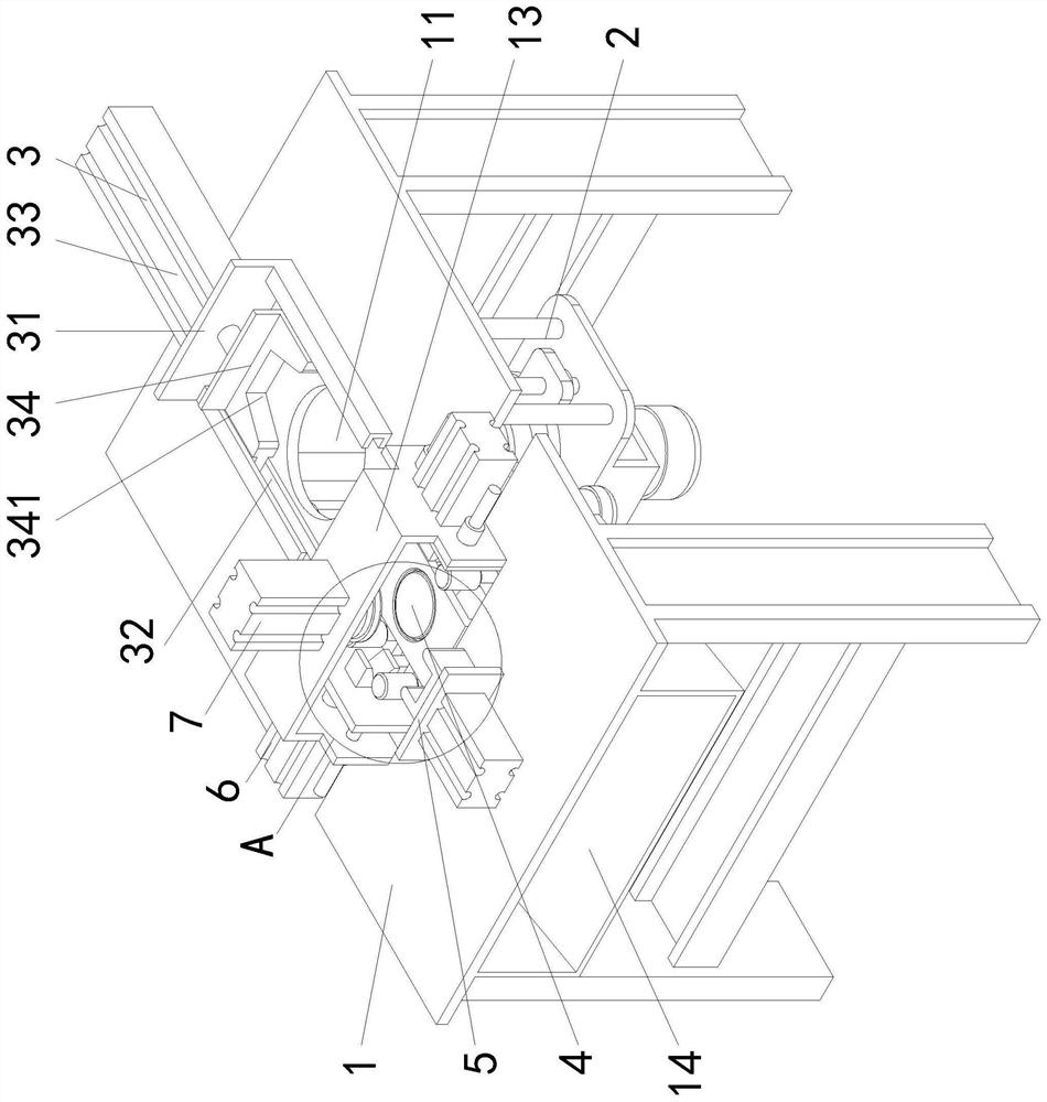
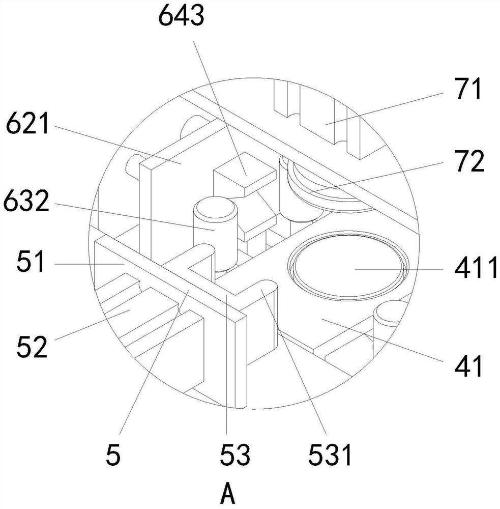
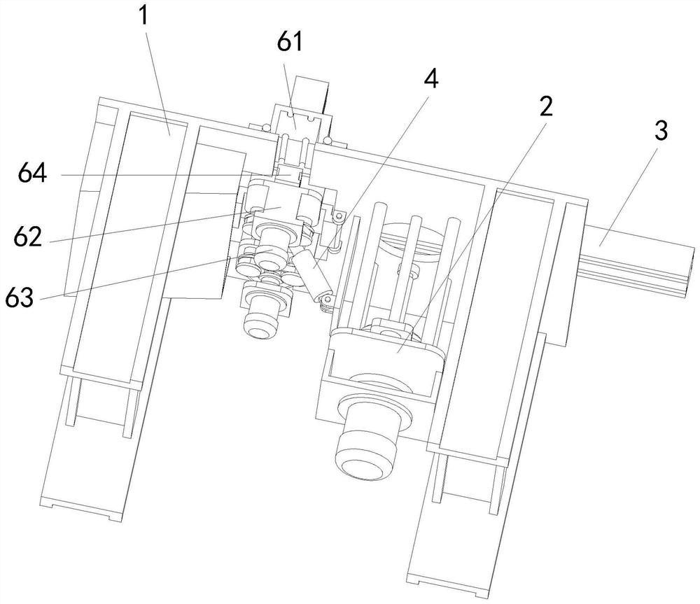
[0039] See attached Figure 1-11 As shown, an optical lens manufacturing and processing system includes a machine 1, an automatic feeding mechanism 2 for vertically conveying circular lenses, a pushing mechanism 3 for horizontally pushing circular lenses, a discharge pallet mechanism 4, The front gear positioning assembly 5, the chamfering mechanism 6 and the pressing mechanism 7; wherein:

[0040] A round hole 11 and a rectangular hole 12 are arranged on the table surface of the machine 1, and a gantry 13 is also arranged on the upper end of the machine 1...


PUM


Abstract

The invention relates to an optical lens manufacturing and machining system which comprises a machine table, an automatic feeding mechanism used for vertically conveying circular lenses, a pushing mechanism used for horizontally pushing the circular lenses, a discharging supporting plate mechanism, a front blocking positioning assembly, a chamfering mechanism and a pressing mechanism. According tothe optical lens manufacturing and machining system provided by the invention, a series of continuous automatic machining operations of automatic upward conveying, automatic horizontal pushing, automatic chamfering positioning, automatic chamfering machining and automatic discharging of the lenses can be completed through mutual cooperation of the arranged mechanisms, and a traditional manual machining mode is replaced, so that the labor cost is saved, the machining treatment efficiency is greatly improved, the machining precision is controllable and unified, and the overall machining qualityis greatly improved.

Description

technical field [0001] The invention relates to the technical field of optical lens manufacturing and processing, and specifically proposes an optical lens manufacturing and processing system. Background technique [0002] Optical glass is mixed with oxides of high-purity silicon, boron, sodium, potassium, zinc, lead, magnesium, calcium, barium, etc. according to a specific formula, melted at high temperature in a platinum crucible, stirred evenly with ultrasonic waves, and removed air bubbles; Slowly cool down over time to avoid internal stress in the glass block. The cooled glass block is then measured by optical instruments to check whether the purity, transparency, uniformity, refractive index and dispersion rate meet the specifications; the qualified glass block will be processed by heating and forging into optical lens blanks. [0003] The raw materials of optical lens blanks will be further processed through milling, fine grinding, polishing, edging, coating, ink coa...

Claims


Application Information

Patent Timeline
Patent Type & Authority Applications(China)
IPC IPC(8): B24B9/14B24B27/00B24B41/00B24B41/06B24B47/12B24B47/22
CPCB24B9/14B24B9/146B24B27/0076B24B41/005B24B41/06B24B47/12B24B47/22
Inventor 倪娅丹高亚芳
Owner 福源中山光电科技有限公司
Learn More