Inverter circuit
A converter and circuit technology, which is applied to the use of electric light sources, electrical components, gas discharge lamps, etc., can solve the problems of increasing the number of components used and increasing the cost.
- Summary
- Abstract
- Description
- Claims
- Application Information
AI Technical Summary
Problems solved by technology
Method used
Image

Examples
Embodiment approach 1
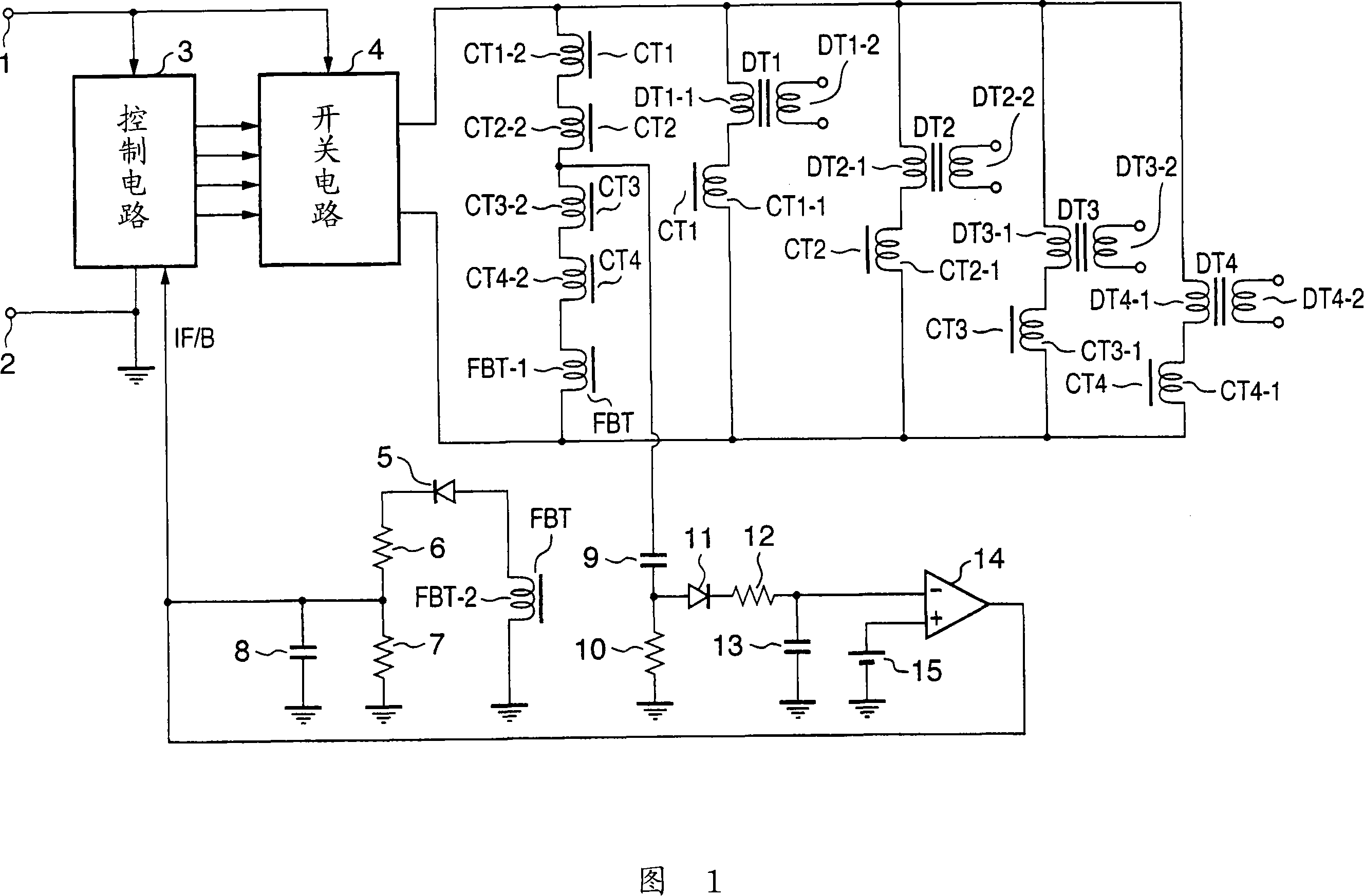
[0023] FIG. 1 is a circuit diagram of an inverter circuit using an even number of drive transformers according to Embodiment 1 of the present invention. In the converter circuit of FIG. 1 , a DC power supply voltage Vin is supplied between a terminal 1 and a terminal 2 . The DC power supply voltage Vin is supplied to the control circuit 3 and the switch circuit 4 as a DC operating power supply.
[0024] The control circuit 3 includes an oscillation circuit inside, and supplies switching pulses to the switching circuit 4 . In addition, the switch circuit 4 generates a high-frequency drive signal by switching the DC power supply voltage Vin in response to a switch pulse supplied from the control circuit 3 . Therefore, the switch circuit 4 includes a switch element composed of a plurality of bipolar transistors or FET transistors.
[0025] In addition, the converter circuit in FIG. 1 has four driving transformers DT1 to DT4 , four balancing transformers CT1 to CT4 and one feedb...
Embodiment approach 2
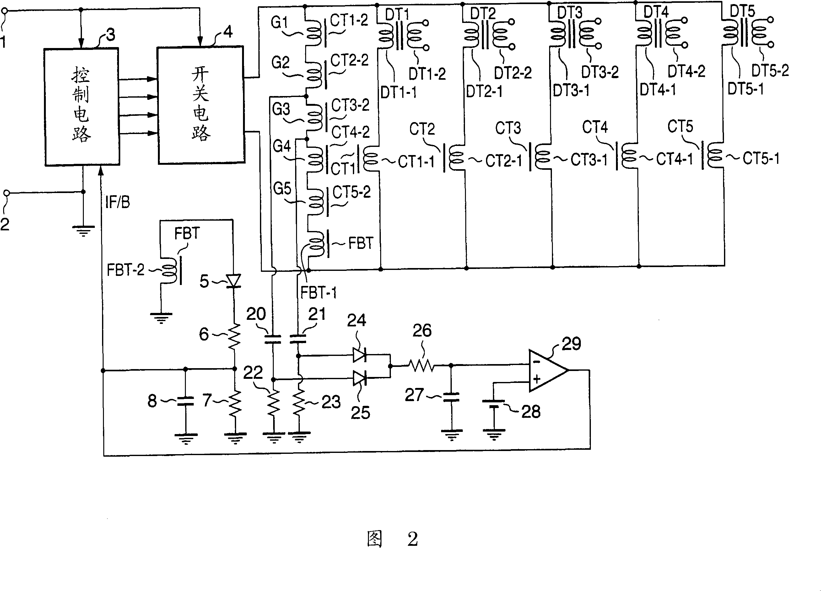
[0042] 2 is a circuit diagram of an inverter circuit using an odd number of drive transformers according to Embodiment 2 of the present invention. In addition, in FIG. 2, the same code|symbol is used for the same circuit element. In the inverter circuit of FIG. 2 , as in the inverter circuit of FIG. 1 , the DC power supply voltage Vin is supplied between the terminal 1 and the terminal 2 . The DC power supply voltage Vin is supplied to the control circuit 3 and the switch circuit 4 as a DC operating power supply.
[0043] The control circuit 3 has the same configuration and performs the same operation as the control circuit 3 shown in FIG. 1 , and thus description thereof will be omitted.
[0044] The converter circuit according to Embodiment 2 includes five drive transformers DT1 to DT5 , five balance transformers CT1 to CT5 , and one feedback transformer FBT. As shown in FIG. 2, the secondary coils CT1-2 to CT5-2 of the five balance transformers CT1 to CT5 and the primary ...
PUM
 Abstract
Description
Claims
Application Information
 - R&D
- Intellectual Property
- Life Sciences
- Materials
- Tech Scout
- Unparalleled Data Quality
- Higher Quality Content
- 60% Fewer Hallucinations
Browse by: Latest US Patents, China's latest patents, Technical Efficacy Thesaurus, Application Domain, Technology Topic, Popular Technical Reports.
© 2025 PatSnap. All rights reserved.Legal|Privacy policy|Modern Slavery Act Transparency Statement|Sitemap|About US| Contact US: help@patsnap.com