
Air outlet duct system

A technology for exhaust pipes and exhaust gas, which is applied to exhaust devices, mechanical equipment, engine components, etc., and can solve problems such as cooling water overflow

Inactive Publication Date: 2011-08-10
MAN ENERGY SOLUTIONS SA
View PDF1 Cites 0 Cited by
  • Summary
  • Abstract
  • Description
  • Claims
  • Application Information

AI Technical Summary

Problems solved by technology

The large relative movements between the exhaust pipe sections of the exhaust pipe system therefore create the risk that the cooling water flow channels at the transition between two adjacent exhaust pipe sections are no longer sufficiently sealed, This creates the risk of cooling water overflowing

Method used


Image

  • Air outlet duct system
  • Air outlet duct system
  • Air outlet duct system

Examples


Embodiment Construction

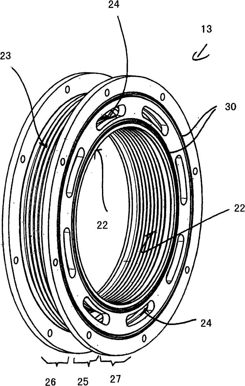
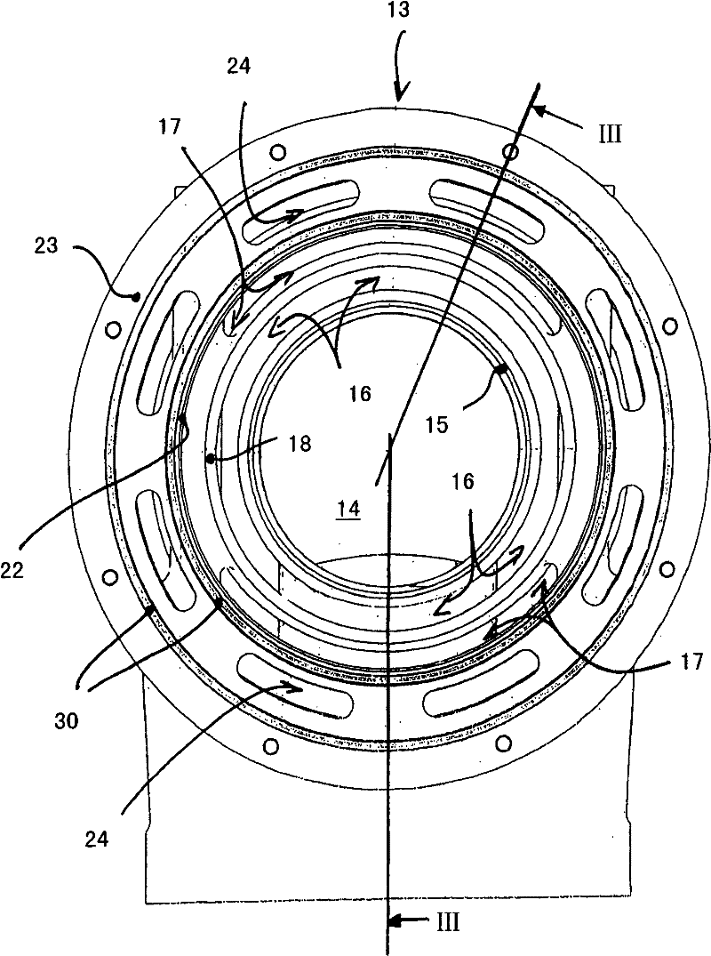
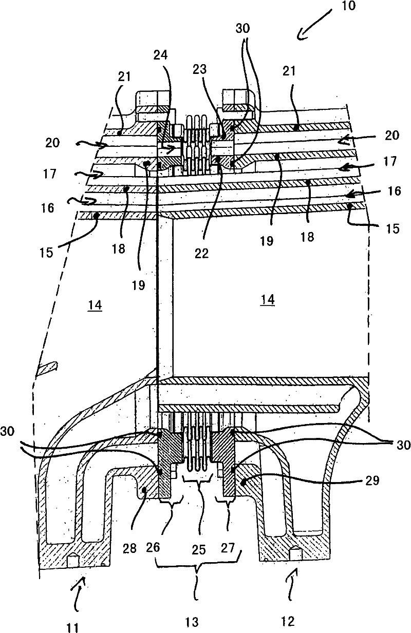
[0034] The invention relates to an exhaust pipe system for a multi-cylinder internal combustion engine, which is assembled from a plurality of exhaust pipe sections. Such an exhaust pipe system consisting of a plurality of exhaust pipe sections has basically been disclosed in DE 196 44 707 C2, and the invention here concerns such details of such an exhaust pipe system that even adjacent exhaust pipe Optimal connection between pipe sections. then image 3 The section shows the exhaust pipe system 10 according to the invention in the area of ​​two adjacent exhaust pipe sections 11 , 12 which are closed using an exhaust gas compensator 13 interconnected. figure 1 A perspective overall view of such an exhaust gas compensator 13 is shown. figure 2 explained image 3 Section direction III-III of the section.

[0035] from image 3 As can be seen from FIG. 2 , each of the two exhaust pipe sections 11 and 12 includes an exhaust gas flow channel 14 which is defined by the tubula...


PUM


Abstract

The invention relates to a discharge pipe system used for the multiple cylinder internal combustion engine, including a plurality of discharge pipes, wherein each discharge pipe segment has a joint flange for jointing the corresponding discharge pipe segment to the cylinder of the internal combustion engine, and each discharge pipe segment also has an exhaust gas flow passage, at least two exhaust gas longitudinal chambers surrounding the exhaust gas flow passage and a cooling water flow passage surrounding the exhaust gas flow passage and the exhaust gas longitudinal chambers. Two adjacent discharge pipe segments are assembled in the condition of using the exhaust gas compensator so that the exhaust gas flow passage of the discharge pipe segment and the first exhaust gas longitudinal chamber of the discharge pipe segment surrounding the corresponding exhaust gas flow passage are directly complemented and the second gas exhaust longitudinal chamber of the gas exhaust segment surrounding the corresponding first gas exhaust longitudinal chamber and cooling water flow passage of the gas exhaust segment surrounding the second gas exhaust longitudinal chamber are complemented from eachother when the exhaust gas compensator is arranged in the center.

Description

technical field [0001] The invention relates to an exhaust pipe system for a multi-cylinder internal combustion engine, which has a plurality of exhaust pipe sections, wherein each exhaust pipe section has a connecting flange for connecting the respective exhaust pipe section to a cylinder of the internal combustion engine, Each exhaust pipe section also has an exhaust gas flow channel, at least two exhaust gas longitudinal chambers each surrounding the exhaust gas flow channel, and a cooling water flow channel surrounding the exhaust gas flow channel and the exhaust gas longitudinal chamber. Background technique [0002] An exhaust pipe system for a multi-cylinder internal combustion engine is known from DE 196 44 707 C2, which is assembled from a plurality of exhaust pipe sections. Each exhaust pipe section of the exhaust pipe system disclosed there has a connecting flange for connecting the exhaust pipe section to a cylinder head connection of a cylinder of an internal co...

Claims


Application Information

Patent Timeline
Patent Type & Authority Patents(China)
IPC IPC(8): F01N7/08F02F1/42F01N13/18
CPCF01N13/1816F01N3/046Y02T10/20Y02T10/12F01N13/143F01N13/00F01N13/08
Inventor M·桑根
Owner MAN ENERGY SOLUTIONS SA
Learn More