Short cold crucible for continuous melting and directional solidification flat blank

A directional solidification, cold crucible technology, applied in crucible furnaces, furnace types, furnaces, etc., can solve the problems of discontinuous melt melting, low power utilization, poor melt melting, etc., to achieve good magnetic permeability and reduce energy consumption. , easy to observe and control the effect

Inactive Publication Date: 2008-02-13
HARBIN INST OF TECH
View PDF0 Cites 8 Cited by
  • Summary
  • Abstract
  • Description
  • Claims
  • Application Information

AI Technical Summary

Problems solved by technology

[0003] In order to solve the problems of the existing electromagnetic cold crucible that the melt is attached to the inner wall of the crucible, the melting of the melt is discontinuous, the melting of the melt is poor, the composition is uneven, the utilization rate of electric energy is low, and it is inconvenient to observe, and further provides a Short cold crucible for continuous melting and directional solidification of slabs

Method used


Image

  • Short cold crucible for continuous melting and directional solidification flat blank
  • Short cold crucible for continuous melting and directional solidification flat blank

Examples


specific Embodiment approach 1

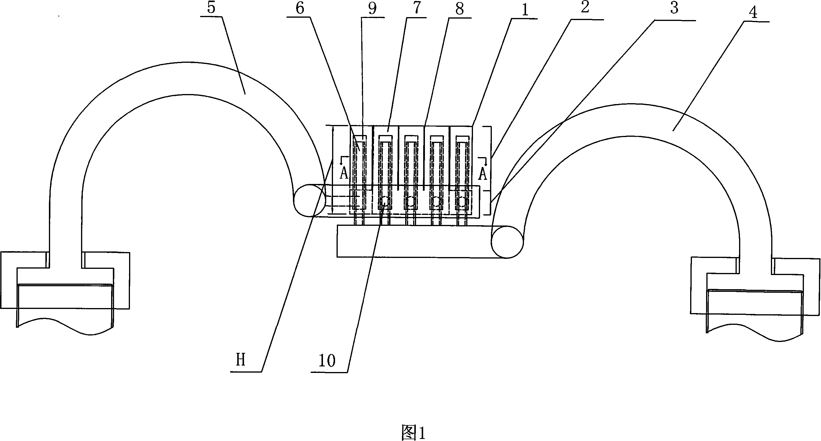
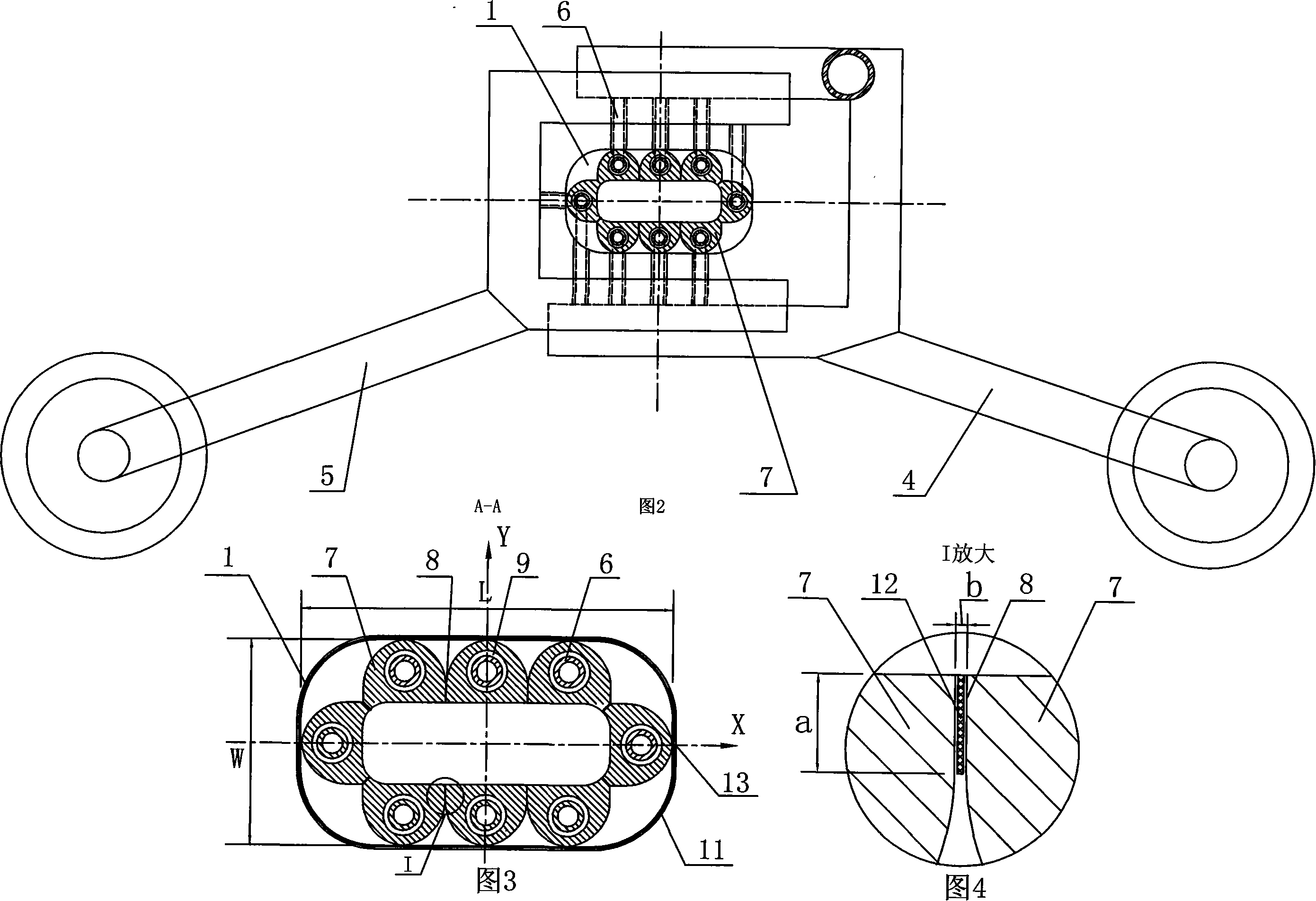
[0007] Embodiment 1: As shown in Figures 1 to 3, the short cold crucible for continuous melting and directional solidification slabs described in this embodiment consists of a water inlet pipe 4, a water outlet pipe 5, several fine water pipes 6, and a copper crucible main body 1. Composed of induction coil 13, the water inlet pipe 4 communicates with the copper crucible main body 1 through several thin water pipes 6, the water outlet pipe 5 communicates with the copper crucible main body 1 through several thin water pipes 6, and the induction coil 13 is set on the copper crucible main body 1 on the upper body 2; the cross-section of the copper crucible main body 1 is a flat ring cavity body, the copper crucible main body 1 is composed of the upper half body 2 and the lower half body 3, the upper half body 2 and the lower half body The body 3 is integrated, and the upper body 2 is divided into eight petal-shaped cylinders 7 in cross-section, and the eight petal-shaped cylinders...

specific Embodiment approach 2

[0009] Embodiment 2: The insulating sealing material layer 12 described in this embodiment is composed of natural mica sheet and epoxy resin. Choose such materials, the sealing and insulating effect is the best. Other compositions and connections are the same as in the first embodiment.

specific Embodiment approach 3

[0010] Specific embodiment three: as shown in Figures 1 to 3, the thin water pipe 6 and the water inlet pipe 4, the thin water pipe 6 and the water outlet pipe 5, and the thin water pipe 6 and the lower body 3 of the copper crucible main body 1 described in this embodiment are welded . Using welding, it can withstand the pressure of at least 10 atmospheres. Other compositions and connections are the same as in the first embodiment.


PUM


Abstract

A short cooling crucible used for billet continuous melting and directional solidification relates to a cooling crucible. The invention solves the problems of a present electromagnetic cooling crucible, including adhesion between a melt and an inner wall of the crucible, discontinuous melt melting, poor melt melting, uneven composition, low power utilization and inconvenient observation. The cross section of a red copper crucible main body (1) mentioned by the invention is a flat annular hollow cavity. The upper half body (2) is segmented into eight columns (7), of which the cross sections are petal shape. Vertical deep holes are arranged on the bottom face of the lower half body (3), corresponding to the position of the columns (7) with petal-shaped cross sections. Clearances (8) are arranged between every two adjacent columns (7) with petal-shaped cross sections. The clearances (8) are filed with insulating seal material layers (12). The invention makes the low cost melting and forming with high purified materials realized. Metals float in a water cooling copper crucible and are in soft contact with the inner wall of the crucible. The strong stirring of the electromagnetic powermakes the melt components even.

Description

Technical field: [0001] The invention relates to a cold crucible. Background technique: [0002] The cold crucible is a crucible made of water-cooled pure copper. Since the crucible is a water-cooled structure, the temperature of the crucible is very low during use, so the crucible itself hardly pollutes the materials in the crucible. According to the different heating methods of the crucible, it can be divided into non-slit external heating crucible and slotted induction heating crucible. The external heating cold crucible relies on the energy generated by the energy generator to melt the material, while the induction melting cold crucible relies on Electromagnetic induction heating and melting materials, also known as electromagnetic cold crucibles, are currently widely used cold crucibles. Electromagnetic cold crucible technology is a new technology emerging in recent years. It puts the split water-cooled copper crucible in the alternating electromagnetic field, uses the...

Claims


Application Information

Patent Timeline
Patent Type & Authority Applications(China)
IPC IPC(8): F27B14/06F27B14/08F27B14/10
CPCY02P10/25
Inventor 陈瑞润丁宏升郭景杰毕维生苏彦庆傅恒志
Owner HARBIN INST OF TECH
Why Eureka
Try Eureka