Gas cylinder or oil cylinder with self-locking device

A technology of self-locking device and cylinder, applied in the direction of fluid pressure actuating device, etc., can solve the problems of limited self-locking force, causing accidents, unable to open synchronously with active power, etc., and achieves the effect of simple structure and good self-locking effect.

Inactive Publication Date: 2008-02-27
夏培根
View PDF0 Cites 19 Cited by
  • Summary
  • Abstract
  • Description
  • Claims
  • Application Information

AI Technical Summary

Problems solved by technology

[0002] The air cylinder or oil cylinder in the prior art is in a static state when the pressure load is unloaded. At this time, if it is subjected to an external force, passive displacement may occur. In many workplaces, this displacement is not allowed, especially when it involves In the case of personal safety, the passive displacement of the cylinder or oil cylinder will cause losses or even accidents in production
Although some cylinders or oil cylinders also adopt methods such as solenoid valve self-locking and spring self-locking, there are still defects that the self-locking force is limited and cannot be opened synchronously with the main force.

Method used


Image

  • Gas cylinder or oil cylinder with self-locking device

Examples


Embodiment Construction

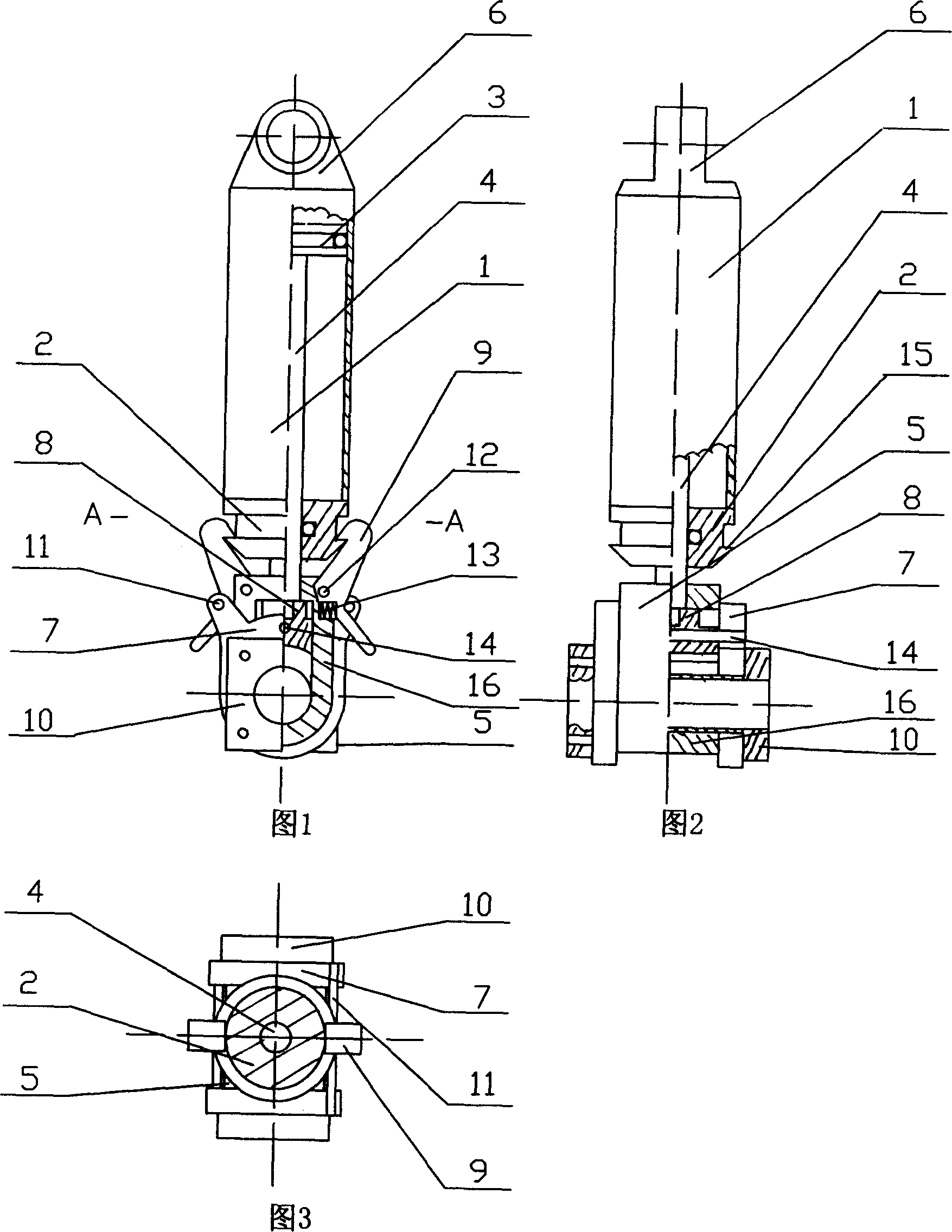
[0011] Referring to Fig. 1, Fig. 2 and Fig. 3, the present invention works like this: the cylinder body 1 is hinged to the fixed end through the lifting lug 6, and the bearing part is connected to the flange shaft 10.

[0012] The opening process of the self-locking device: the pressure medium enters the upper part of the piston 3, pushes the piston 3, and the piston rod 4 starts to move downward, and the slider 8 connected to the end of the piston rod 4 slides in the lock seat 16. The shaft 14 is fixed on both sides of the slider 8, and a shift rod 11 is connected between the two shift forks 7, so the slider 8, shift fork 7, shift rod 11 and piston rod 4 move downward at the same time, and the shift rod 11 presses the lock hook 9 rotates around the pin shaft 12, the upper part of the lock hook 9 is disengaged from the slot 15 on the cylinder head 2, and the lower part presses the spring 13, because there is a gap between the slider 8, the shift fork 7 and the flange shaft 10, ...


PUM


Abstract

The present invention discloses one kind of air cylinder or oil cylinder with self-locking device. The air cylinder or oil cylinder includes one cylinder body, one piston rod inside the cylinder body, one cylinder cap, one piston fixed to one end of the piston rod, one lock connected to the end of the piston rod stretched beyond the cylinder cap, and one clamping slot in the outer edge of the cylinder cap. The air cylinder or oil cylinder has self-locking device in simple structure and good self-locking effect, and may be operated only in the presence of driving force caused by air or oil pressure, reaching no malfunction.

Description

technical field [0001] The invention relates to a pneumatic or hydraulic device in the field of mechanical technology, in particular to an air cylinder or oil cylinder with a self-locking device. Background technique [0002] The air cylinder or oil cylinder in the prior art is in a static state when the pressure load is unloaded. At this time, if it is subjected to an external force, passive displacement may occur. In many workplaces, this displacement is not allowed, especially when it involves In the case of personal safety, the passive displacement of the cylinder or oil cylinder will cause losses to production or even cause accidents. Although some cylinders or oil cylinders also adopt methods such as solenoid valve self-locking, spring self-locking, etc., there are still defects that the self-locking force is limited and cannot be opened synchronously with the main force. Contents of the invention [0003] The object of the present invention is to provide a cylinder...

Claims


Application Information

Patent Timeline
Patent Type & Authority Applications(China)
IPC IPC(8): F15B15/26
Inventor 夏培根
Owner 夏培根
Why Eureka
Try Eureka