
Box type transformer station

A box-type substation and transformer room technology, applied in substations, enclosed substations, substation/switch layout details, etc., can solve the problems of poor natural heat dissipation performance, increased manufacturing cost and maintenance difficulty, and large equipment damage.

Active Publication Date: 2016-07-13
袁茂银
View PDF18 Cites 0 Cited by
  • Summary
  • Abstract
  • Description
  • Claims
  • Application Information

AI Technical Summary

Problems solved by technology

The semi-buried box-type substation puts the transformer under the ground, so the volume of the box-type substation on the ground is greatly reduced, but because the transformer is placed under the bottom, the predictability of safety accidents is not strong, and the humid underground environment will cause great damage to the equipment. The moisture in the foundation foundation also has a great impact on the equipment, and it is more likely to cause safety accidents in rainy seasons
[0006] 2. Compact box-type substation, this kind of box-type substation mainly reduces its volume and floor area at the same time, and the reduction of floor space is achieved by its volume reduction, but it is still unavoidable to install the foundation
[0019] It is not difficult to see that in order to maintain better heat dissipation performance, the above-mentioned transformers are forced to dissipate heat by external force, while natural heat dissipation is often limited by the structural layout of the box-type substation itself, and cannot form a natural heat dissipation system with good convection. Never having to rely on the above-mentioned forced heat dissipation equipment, the equipment in the box-type substation increases, which leads to an increase in production costs and maintenance difficulties. In addition, the above-mentioned various auxiliary heat dissipation equipment has low environmental versatility, often due to the environment in which the box-type substation is located. Due to the limitation, it cannot play its best heat dissipation effect, what is more, it may not be applicable at all
[0020] To sum up, the current box-type substations on the market have many problems such as large size, inconvenient maintenance, poor natural heat dissipation performance, and poor environmental adaptability, which also restricts the promotion of box-type substations in my country to a certain extent.

Method used


Image

  • Box type transformer station
  • Box type transformer station
  • Box type transformer station

Examples


Embodiment 1

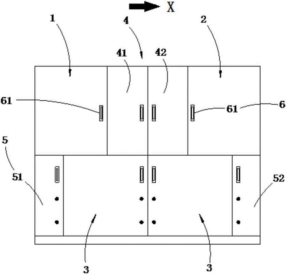
[0108] The invention provides a box-type substation, figure 1 and figure 2 It is the front view and perspective view of the box-type substation, such as figure 1 As shown: the box-type substation is equipped with a high-voltage switch room 1, a low-voltage switch room 2, a transformer room 3, a metering room 4 and a cable room 5. The metering room 4 can also be used as a high-voltage and low-voltage connection area, and the cable room 5 includes high-voltage cables. Room 51 and low-voltage cable room 52; it should be noted that the metering room can be one, and the high-supply high meter or high-supply low meter method is used to save corresponding functional equipment and simplify its structure. It can be called a high-voltage metering room or a low-voltage metering room. Metering room; what adopt in the present embodiment is that high-voltage metering (connection) room 41 and low-voltage metering room 42 can be used as metering cooperation, and wherein high-voltage meter...

Embodiment 2

[0113] The only difference between this embodiment and embodiment 1 is that the cable chamber 5, Figure 3-6 is a schematic diagram of the box-type substation, such as image 3 As shown, there is a two-layer structure between the high-voltage cable room 51 and the low-voltage cable room 52. Along the X direction, the upper layer is the high-voltage switch room 1, the metering room 4 and the low-voltage switch room 2, and the lower layer is the transformer room 3; the high-voltage cable room 51 and the low-voltage cable chamber 52 are the same height as the two-layer structure respectively. The improvement of the structure of the cable room 5 can realize that the incoming cables of the box-type substation can be fed in both up and down, and can be expanded to be applicable to situations such as overhead lines that need to be fed in from the top of the box-type substation. Such as Figure 4 As shown, at this time, the incoming cable enters the line from the bottom of the box-t...

Embodiment 3

[0115] The difference between this embodiment and Embodiment 1 is that the bottom surfaces of the high and low voltage switch rooms of the box-type substation in this embodiment are not attached to the top surface of the transformer room respectively, and the side walls of the high and low voltage switch rooms are respectively in contact with the two sides of the transformer room. side walls, such as Figure 7 As shown, as a preferred embodiment, the side wall of the high-voltage switch room 1 in the box-type substation is in close contact with the side wall of the transformer room 3. Similarly, the side wall of the low-voltage switch room 2 is in contact with the side wall of the transformer room 3. The side walls are attached to each other. In addition, the bottom surface of the high-voltage and low-voltage switch rooms is not flush with the top or bottom surface of the transformer room but parallel; The character-shaped structure in the box-type substation is similar, but s...


PUM


Abstract

The invention discloses a box type transformer station. The box type transformer station at least comprises a high-voltage switch chamber, a low-voltage switch chamber and a transformer chamber, wherein the high-voltage switch chamber, the low-voltage switch chamber and the transformer chamber are in echelonment distribution, and equipment lines in the high-voltage switch chamber, the low-voltage switch chamber and the transformer chamber are M-shaped, U-shaped or V-shaped. Different from prior arts, the box-type transformer station enables the volume of the box type transformer station to be reduced by 1 to 3 times compared to a conventional transformer station through innovative adoption of an upper-lower multilayer distribution structure, reduces the area of occupied land, facilitates transportation and decreases the transport cost; and a downward pedestal of the conventional box type transformer station does not have to be manufactured, such that the difficulty of a construction project is reduced, the cost is decreased, and unfavorable influences brought by moisture in the half-embedded pedestal to each device in the box type transformer station can be better avoided.

Description

technical field [0001] The invention relates to a substation, in particular to a box-type substation, which belongs to the technical field of electrical equipment. Background technique [0002] The box-type substation is a substation that organically combines functions such as high-voltage power receiving, transformer step-down, and low-voltage power distribution, and is installed in a fully enclosed, movable steel structure box. Box-type substation has a series of advantages such as strong complete set, short power transmission cycle, strong environmental adaptability, convenient installation, safe and reliable operation, less investment and quick effect, so box-type substation has been widely used in urban network construction and transformation public power distribution. With the acceleration of the modernization process of municipal construction, the box-type substation will gradually replace the original civil power distribution room and become a new type of complete p...

Claims


Application Information

Patent Timeline
IPC IPC(8): H02B7/00H02B1/20H02B1/56H01F27/08H02B1/46
CPCH02B1/202H02B1/46H02B1/565H02B7/00H01F27/085
Inventor 袁茂银
Owner 袁茂银
Learn More