Mixing delivery over-flow valve double seal assistant

An overflow valve and double-seal technology, applied in safety valves, balance valves, valve devices, etc., can solve the problems of equipment vibration, failure to guarantee valve sealing, stability, safety, etc., achieve high safety and improve production Efficiency and safety performance, the effect of a wide range of applications

Inactive Publication Date: 2008-03-05
SOUTH CHINA UNIV OF TECH
View PDF0 Cites 2 Cited by
  • Summary
  • Abstract
  • Description
  • Claims
  • Application Information

AI Technical Summary

Problems solved by technology

[0002] For the multi-phase mixed transportation conditions of various fluid media with high pressure, large flow and large viscosity r

Method used


Image

  • Mixing delivery over-flow valve double seal assistant
  • Mixing delivery over-flow valve double seal assistant

Examples


Example Embodiment

[0015] Example one

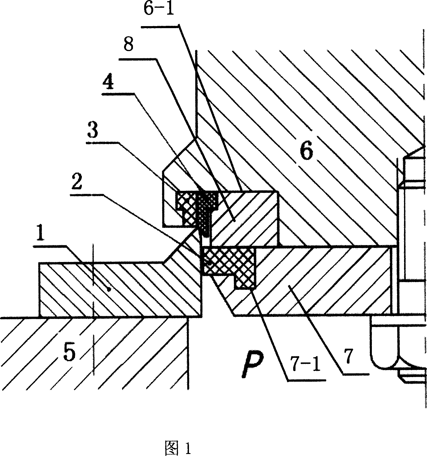
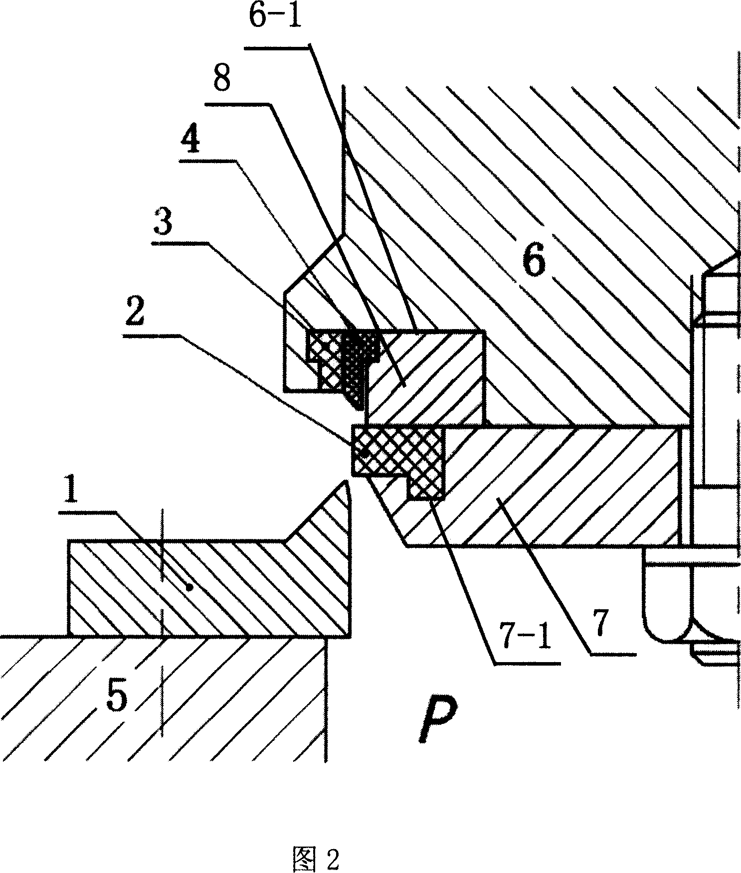
[0016] As shown in Figures 1 and 2, the double sealing pair of this mixed transport overflow valve includes an upper sealing pair and a lower sealing pair 1, which are arranged oppositely. The upper sealing pair is arranged at the lower end of the valve core, and the lower sealing pair 1 is fixedly installed on the valve body 5. The upper and lower sealing pair 1 is provided with a flange along the upper end of the inner circumference, and its section is knife-edge. The upper sealing pair includes a sealing ring 2, a ferrule 3, and a sealing ring 4. The sealing ring 2 is fixed under the valve core 6 by a fixing block 7 On the end face, the sealing ring 2 is embedded in the upper ring groove 7-1 of the fixed block 7; the sealing ring 4 is embedded in the lower ring groove 6-1 on the lower end surface of the valve core 6 through the ferrule 3 and the fixed ring 8, the ferrule 3 is located on the outer circumference of the sealing ring 4, the fixed ring 8 is loca...


PUM


Abstract

This invention provides a double sealing pair of mixed transportation overflow valve containing corresponding upper and lower sealing pair. The upper sealing pair is positioned at the lower end of the valve core, and the lower sealing pair is fixed on the valve body. The lower sealing pair has flange at the top of inner lumen with a blade-shaped section. The upper sealing pair includes seal circle, ferrule and seal ring. The seal ring is positioned at the bottom face of the valve core via the fixing block and embedded in the upper ring groove of the fixing block. The seal circle is embedded in the lower ring groove on the bottom face of the valve core via the outer ferrule and the inner fixing ring. An inverted conical face is set at the bottom of the external of the lower sealing pair. When the valve is closed, the external of the seal ring is coupled with the lower sealing pair, the flange of the lower sealing pair contacts with the bottom of the ferrule. The invention has high sealing performance, stability and safety.

Description

technical field [0001] The invention relates to an auxiliary component of a mixed transmission relief valve, in particular to a double sealing pair of a mixed transmission relief valve. Background technique [0002] For the multi-phase mixed transportation conditions of various fluid media with high pressure, large flow and large viscosity range, the traditional sealing pair cannot guarantee the sealing, stability and safety of the valve, and will cause equipment vibration. In order to ensure that the mixed transmission relief valve can achieve the required pressure stabilization accuracy and work stability under the design pressure, flow rate and medium viscosity range, so as to improve the production efficiency and safety performance of the mixed transmission system, it is necessary to design a high-performance sealing pair . Contents of the invention [0003] The purpose of the present invention is to overcome the shortcomings and deficiencies of the above-mentioned pr...

Claims


Application Information

Patent Timeline
IPC IPC(8): F16K17/02
Inventor 杨凯徐忠阳林富春毋济海
Owner SOUTH CHINA UNIV OF TECH
Why Eureka
Try Eureka