Supercharge Your Innovation With Domain-Expert AI Agents!

Engine fastener of a mounting system interposed between an attachment strut and an aircraft engine

An aero-engine and assembly system technology, applied in the layout/installation of power plants, aircraft parts, power plant construction, etc., can solve the difficulty of force transmission, unoptimized total weight and size of the main body, unfavorable overall size and weight, etc. problem, to achieve the effect of reducing the length

Inactive Publication Date: 2008-03-12
AIRBUS OPERATIONS (SAS)
View PDF0 Cites 10 Cited by
  • Summary
  • Abstract
  • Description
  • Claims
  • Application Information

AI Technical Summary

Problems solved by technology

[0014] Also, the need to provide this rear exclusively to accommodate the hinge pins of course means that the overall weight and size of the body is not optimized
Moreover, the remote location of the bearings housing the hinge pins necessitates the presence of two very long rods, which is also disadvantageous in terms of the overall size and weight of the front attachment
[0015] Finally, it should be noted that the difference in thickness between the central and rear parts of the attachment body leads to difficulties in transmitting forces in the attachment

Method used


Image

  • Engine fastener of a mounting system interposed between an attachment strut and an aircraft engine
  • Engine fastener of a mounting system interposed between an attachment strut and an aircraft engine
  • Engine fastener of a mounting system interposed between an attachment strut and an aircraft engine

Examples


Embodiment Construction

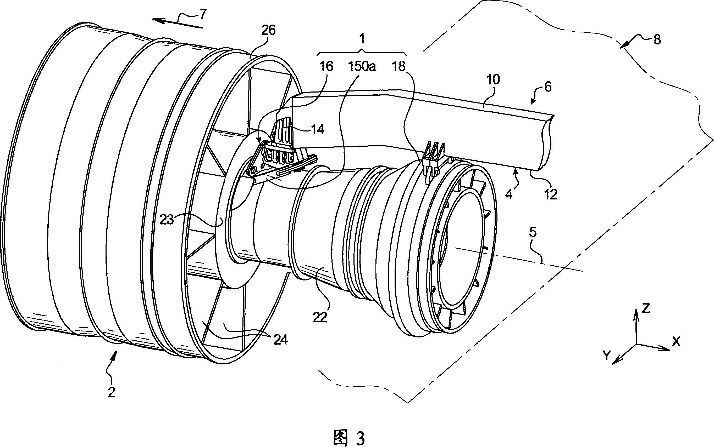
[0040] Referring first to FIG. 3 , there is shown an assembly system 1 in a preferred embodiment of the present invention, wherein the assembly system 1 is installed between an aeroengine 2 and a rigid structure 4 of an accessory strut 6 fixed under the wing of the aircraft, for For reasons of clarity of simplification, the aircraft wing is shown only diagrammatically and generally designated by the reference numeral 8 . It should be noted that the mounting system 1 is suitable for use in combination with a turbojet engine 2 , but, of course, can be designed as a system for suspending any other type of engine, such as a turboprop, within the scope of protection of the invention. Moreover, the application of the assembly system 1 is not limited to the example shown in FIG. 3 , in which the engine 2 is designed to be suspended under the wing 8 of an aircraft.

[0041]Throughout the following description, by convention, the longitudinal direction parallel to the longitudinal axis...


PUM


Abstract

The invention concerns an engine fastener of a mounting system designed to be interposed between a rigid structure of an attachment strut of an aircraft engine and engine, the fastener comprising a main body (130), a control bar mounted articulating on the main body via a pivot bolt (144), as well as two thrust load absorbing link rods each provided with one end connected on the control bar, the main body consisting of a first main bracket (132a) and a second main bracket (132b) superimposed on the first. The invention is characterized in that the pivot bolt (144) consists of a first portion (144a) and a second portion (144b), the first portion being made in one single piece with the first bracket and the second portion being made in one single piece with the second bracket. Moreover, the brackets (132a, 132b) define an abutting surface (166) capable of limiting the rotation of the control bar (146).

Description

technical field [0001] The present invention relates generally to engine accessories of a mounting system designed to fit between the rigid structure of an accessory strut of an aeroengine and the engine, and more particularly (but not exclusively) to a front accessory which is Designed to absorb forces exerted along the longitudinal, lateral and vertical directions of the engine. [0002] The invention also relates to a mounting system designed to be mounted between the rigid structure of an aeroengine accessory strut and the engine, wherein the system can be used regardless of the position of the engine relative to the position of the accessory strut. Background technique [0003] An aircraft accessory strut is provided to facilitate forming a connection interface between an engine and a wing of the aircraft. The accessory struts transmit the forces generated by the aircraft's engines to the aircraft's structure and also allow the passage of fuel, electricity, hydraulics ...

Claims


Application Information

Patent Timeline
Patent Type & Authority Applications(China)
IPC IPC(8): B64D27/26B64D27/40
CPCY02T50/44B64D27/26Y02T50/40B64D27/406B64D27/40
Inventor 雅克·博福尔让-弗朗索瓦·杜蒙特
Owner AIRBUS OPERATIONS (SAS)
Features
  • R&D
  • Intellectual Property
  • Life Sciences
  • Materials
  • Tech Scout
  • Unparalleled Data Quality
  • Higher Quality Content
  • 60% Fewer Hallucinations
Learn More