Imaging equipment

A technology of imaging equipment and imaging devices, applied in printing, printing devices, etc., can solve the problem of inability to accurately control the conveying volume of recording sheets, and achieve the effect of precisely controlling the conveying volume

Inactive Publication Date: 2010-07-28
BROTHER KOGYO KK
View PDF6 Cites 0 Cited by
  • Summary
  • Abstract
  • Description
  • Claims
  • Application Information

AI Technical Summary

Problems solved by technology

Therefore, in some cases, the conveyance amount of the recording sheet cannot be precisely controlled, resulting in banding on the recording sheet.

Method used


Image

  • Imaging equipment
  • Imaging equipment
  • Imaging equipment

Examples


Embodiment Construction

[0041]In an exemplary embodiment of the present invention, the image forming apparatus of the present invention is applied to a multifunctional machine having several functions such as a printing function, a scanning function, a color copying function, and a facsimile function. Exemplary embodiments of the present invention will be described in detail with reference to the accompanying drawings.

[0042] Note that various connections are set forth between elements in the following description. Note: Unless otherwise specified, these connections may generally be direct or indirect; and this description is not intended to be limited in this respect.

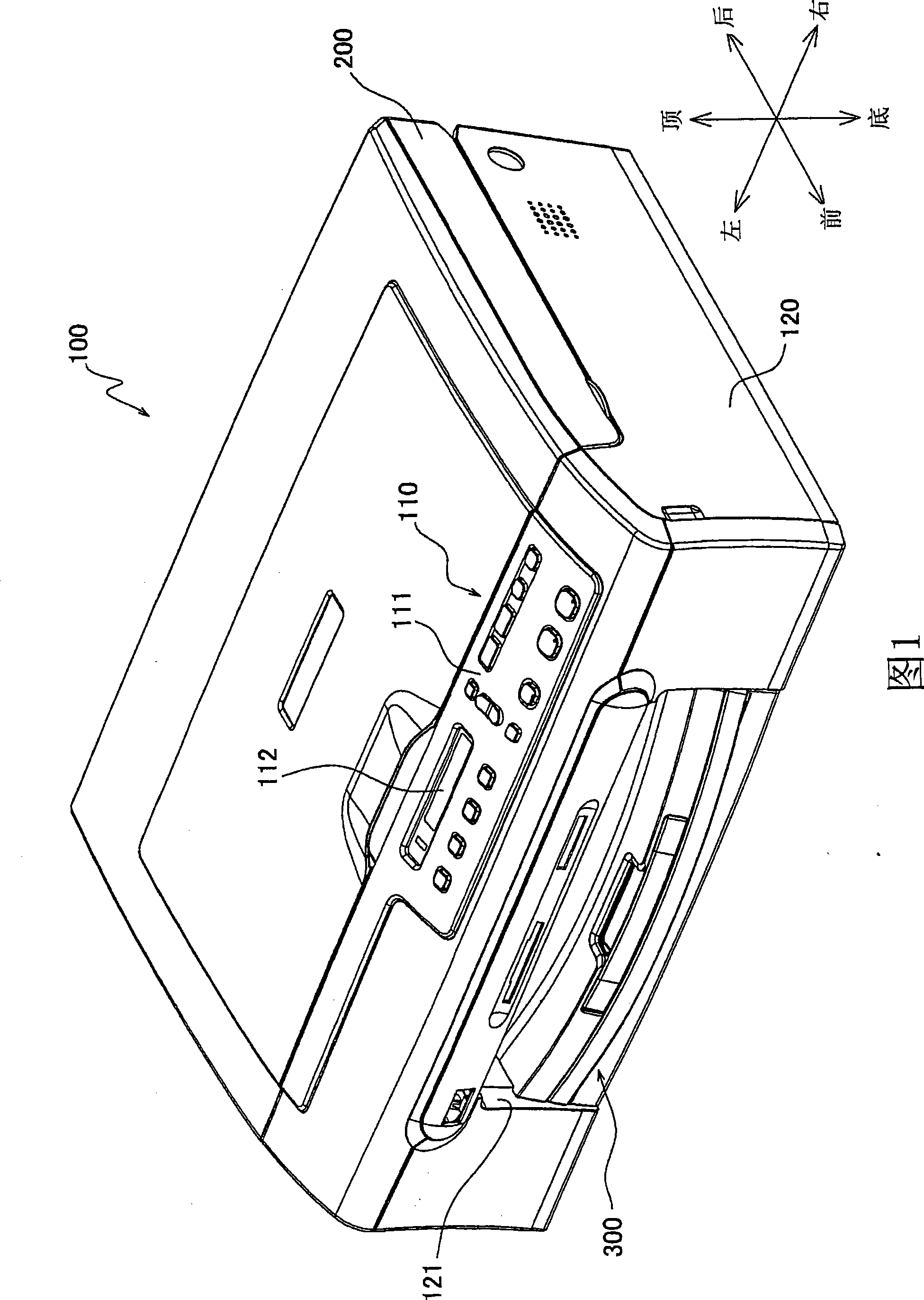
[0043] The general outline of the imaging device 1 will be described below. Such as figure 1 As shown, the image forming apparatus 100 of the first exemplary embodiment of the present invention is installed so that: figure 1 The proximal side is referred to as the front side of the imaging device 100, and figure 1 The top side ...


PUM


Abstract

The invention provides an imaging device comprising: sheet feeding disc for loading the recording sheet; sheet feeding roller for feeding the recording sheet to the imaging device; delivery roller at the downstream of the sheet feeding roller along the shet feeding direction and applying the feeding force to the recording sheet; sheet position detecting device for detecting the position of the recording sheet on the feeding path; and feeding roller control device for controlling the rotation amount of the feeding roller based on the detected position. The said control device allow that the rotation amount of the delivery roller when the recording sheet contacts with the sheet feeding roller and the delivery roller is more than the rotation amount of the delivery roller when the recording sheet can not contact with the sheet feeding roller.

Description

[0001] Cross References to Related Applications [0002] This application claims priority from Japanese Patent Application No. 2006-251331 filed on September 15, 2006, the entire subject matter of which is incorporated herein by reference. technical field [0003] Aspects of the invention relate to an image forming apparatus. In particular, the aspects are effective when employed in an image forming apparatus including an inkjet type image forming device. Background technique [0004] In an inkjet type image forming apparatus (hereinafter, referred to as an inkjet printer), images or text / characters are recorded on a recording sheet in a known manner. For example, when ink is not ejected onto the recording sheet from the recording head, the recording sheet is moved or conveyed. The ink is ejected onto the recording sheet while the recording head is reciprocatingly moved to scan while the recording sheet remains stationary. That is, in an inkjet printer, an image is formed...

Claims


Application Information

Patent Timeline
Patent Type & Authority Patents(China)
IPC IPC(8): B41J11/00B41J11/42
CPCB41J11/0095B41J11/485B41J13/0018
Inventor 井土正俊古闲雄二
Owner BROTHER KOGYO KK
Why Eureka
Try Eureka