Pressing switch

A technology of switches and openings, applied in the direction of electric switches, electrical components, emergency actuators, etc., can solve the problems of thinning and thickening of the push switch

Inactive Publication Date: 2008-03-19
PANASONIC CORP
View PDF2 Cites 2 Cited by
  • Summary
  • Abstract
  • Description
  • Claims
  • Application Information

AI Technical Summary

Problems solved by technology

[0017] Therefore, in order to increase the strength of the operation part, there is a method of increasing the thickness of the operati

Method used


Image

  • Pressing switch
  • Pressing switch
  • Pressing switch

Examples


Embodiment approach

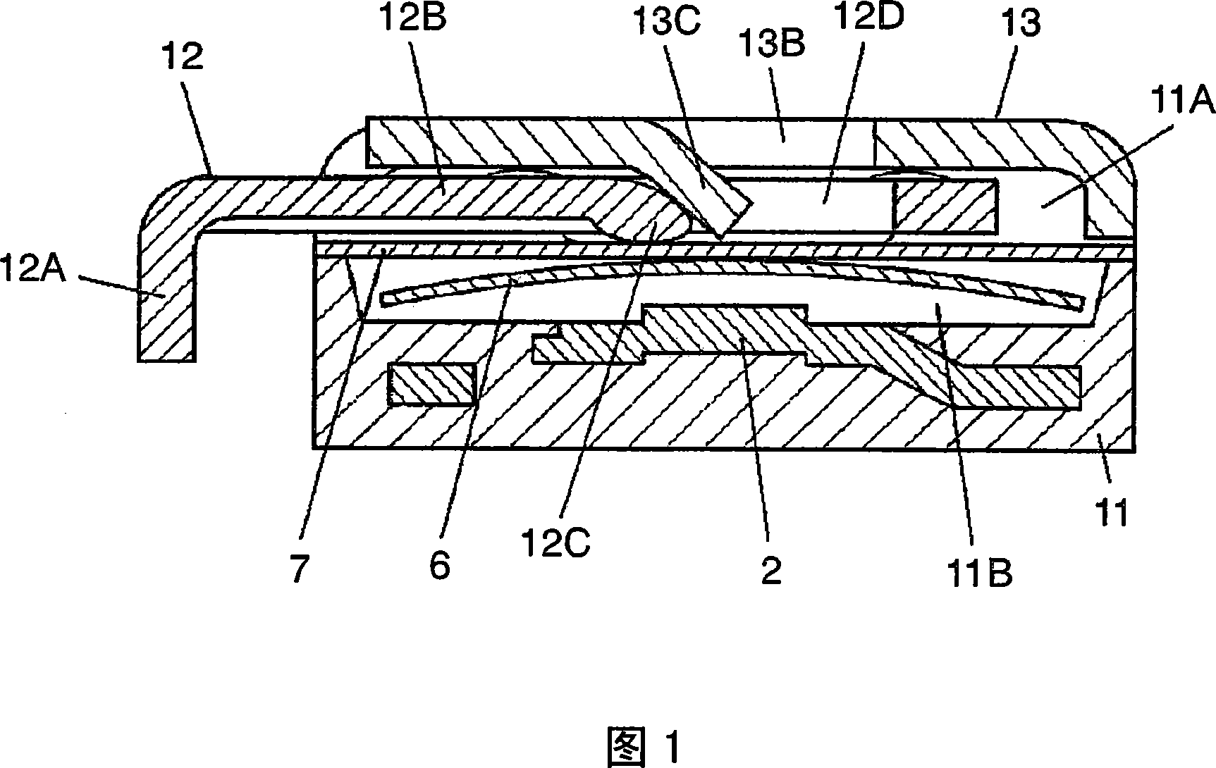
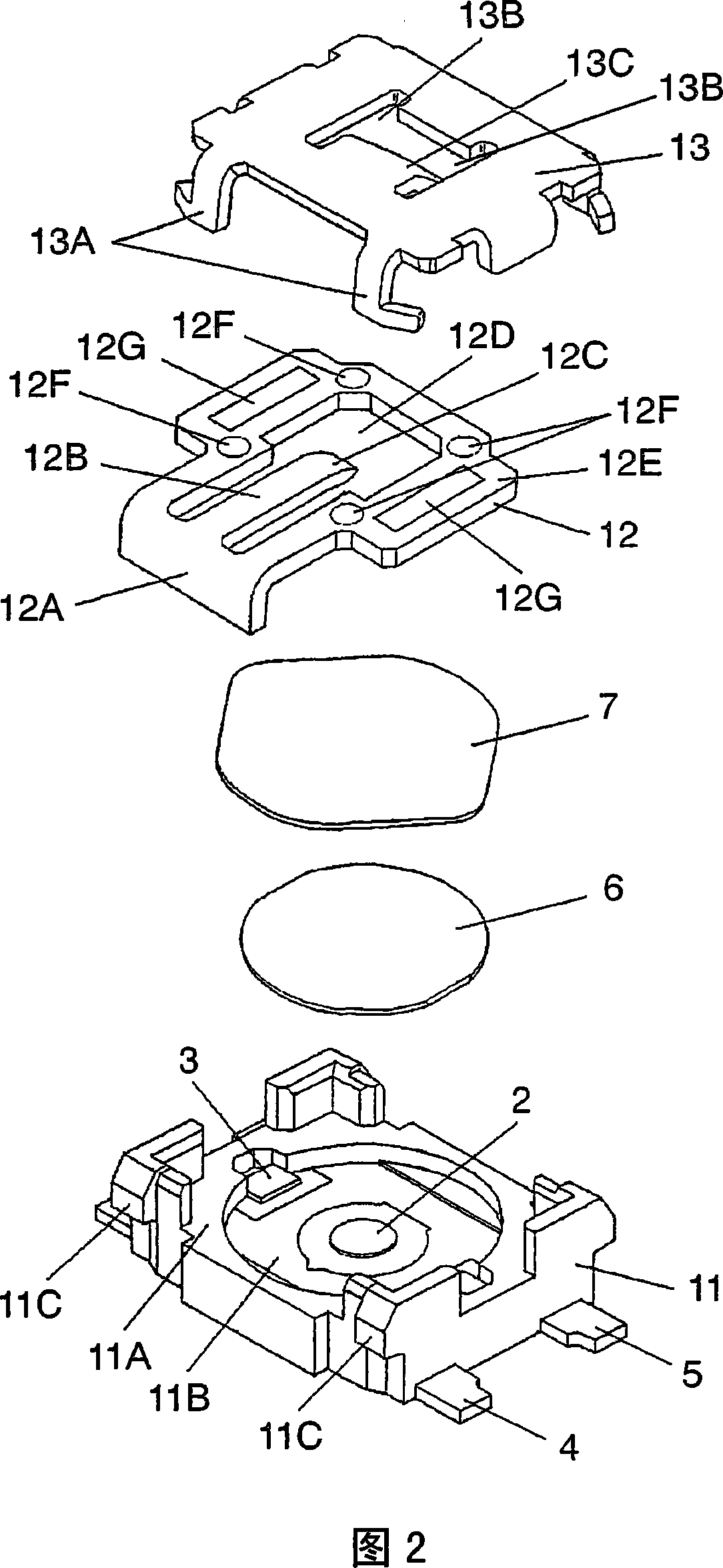
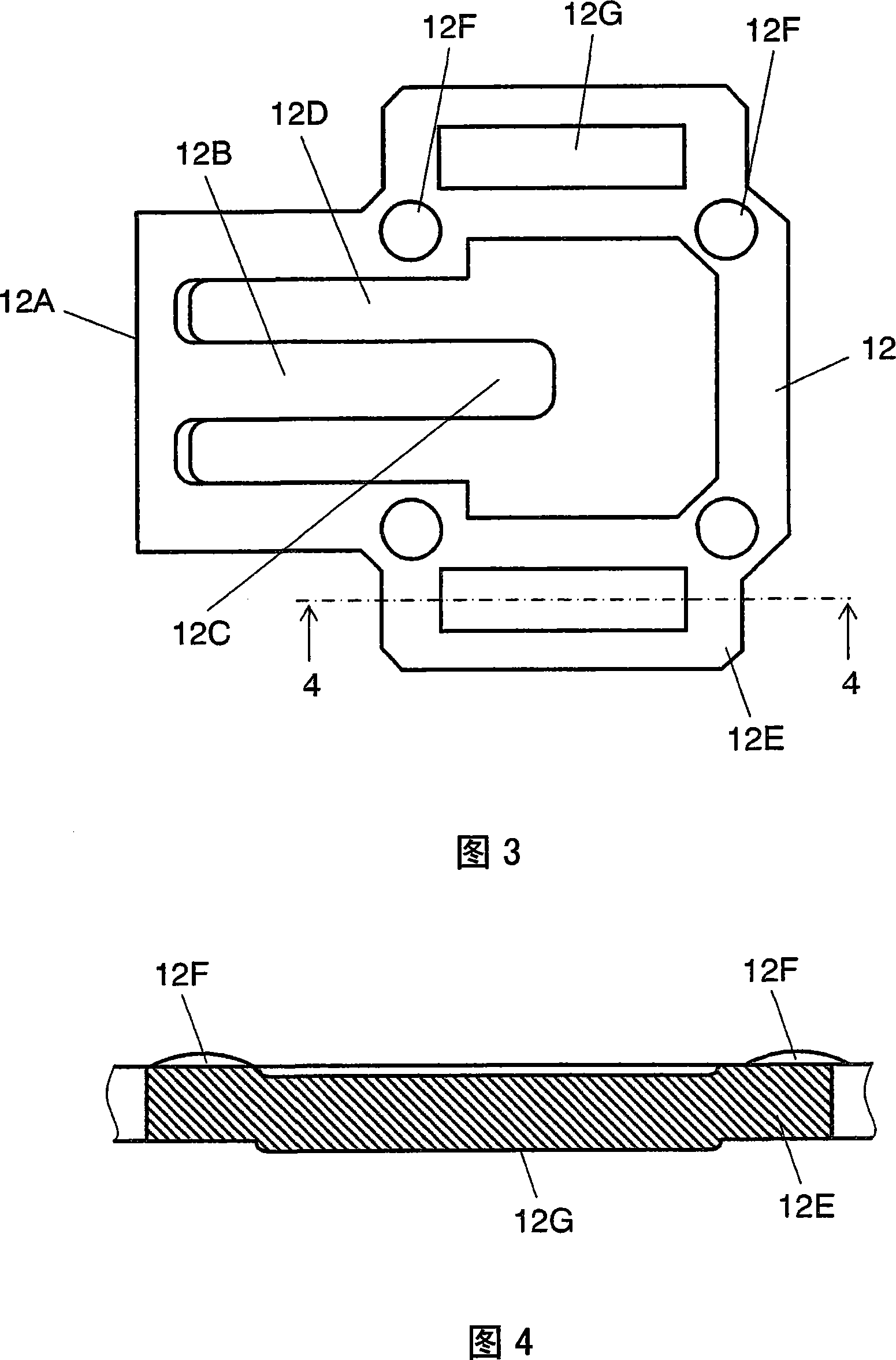
[0034] FIG. 1 is a sectional view of a push switch according to an embodiment of the present invention, and FIG. 2 is an exploded perspective view of the push switch. FIG. 3 is a plan view of the operating body of the push switch, and FIG. 4 is a cross-sectional view taken along line 4-4 in FIG. 3 . In addition, FIG. 5 is a cross-sectional view showing the operating state of the push switch, and FIG. 6 is an external view of an operating body in another embodiment.

[0035] As shown in FIGS. 1 and 2 , the push switch according to this embodiment has a switch case 11 made of a square insulating resin having a substantially circular recess 11B recessed from the bottom surface of an upper opening 11A. constitute. Furthermore, on the inner bottom surface of the recessed portion 11B, the central fixed contact 2 and a pair of outer fixed contacts 3 at an equal distance across the central fixed contact 2 are exposed. In addition, terminals 4 and 5 respectively connected to the cent...


PUM


Abstract

The present invention provides a push switch. An operating body is composed of metal plate, on which setting a resin layer of polyimide, one end of the operating body is arranged with an operating part projecting towards the front outer side of the switch casing, the other end is arranged with arm type drive part and a frame type sliding guide part closing the drive part. The arm type drive part is compressed and pressed to make the board thickness turn thin, setting a hemisphere-shaped upper sliding projecting part contacting with the bottom of a cover on the sliding guide part, as well as a lower sliding projecting part which is longer in front and rear direction and contacts with the lower protecting piece.

Description

technical field [0001] The present invention relates to a push switch that can be operated from a horizontal direction parallel to the wiring board surface of the electronic equipment, which is used in input operation parts of various electronic equipment. Background technique [0002] Various electronic devices have been required to be smaller and thinner as the multi-functionality progresses, represented by mobile phones. Moreover, push switches with a sensitive sense of moderation (feeling of knots) are often used on the input operation part, and push switches are often arranged on the side of the electronic equipment to be able to operate. [0003] A conventional push switch used in an input operation unit of such an electronic device will be described with reference to FIGS. 7 to 10 . [0004] FIG. 7 is a sectional view of a conventional push switch, and FIG. 8 is an exploded perspective view of the push switch. 9 is a cross-sectional view showing the operating state ...

Claims


Application Information

Patent Timeline
IPC IPC(8): H01H13/52H01H13/04H01H13/12H01H13/14
CPCH01H2221/026H01H13/06H01H13/48H01H15/102
Inventor 舛田雅裕屋内康典八木义和
Owner PANASONIC CORP
Why Eureka
Try Eureka