Gas flow generator

A generator and airflow technology, applied in the field of innovative design, can solve the problem of inconvenient application of heat dissipation components, achieve the effect of effective wind-driven heat dissipation, solve the volume problem, and effectively heat dissipation.

Inactive Publication Date: 2008-04-02
SUZHOU FORCECON ELECTRIC
View PDF0 Cites 22 Cited by
  • Summary
  • Abstract
  • Description
  • Claims
  • Application Information

AI Technical Summary

Problems solved by technology

[0005] The present invention provides an airflow generator, the purpose of which is to adopt a heat dissipation component with an innovative structure to solve the problem of inconvenient application of the existing heat dissipation component in the structure of miniaturized electronic communication equipment

Method used


Image

  • Gas flow generator
  • Gas flow generator
  • Gas flow generator

Examples


Embodiment

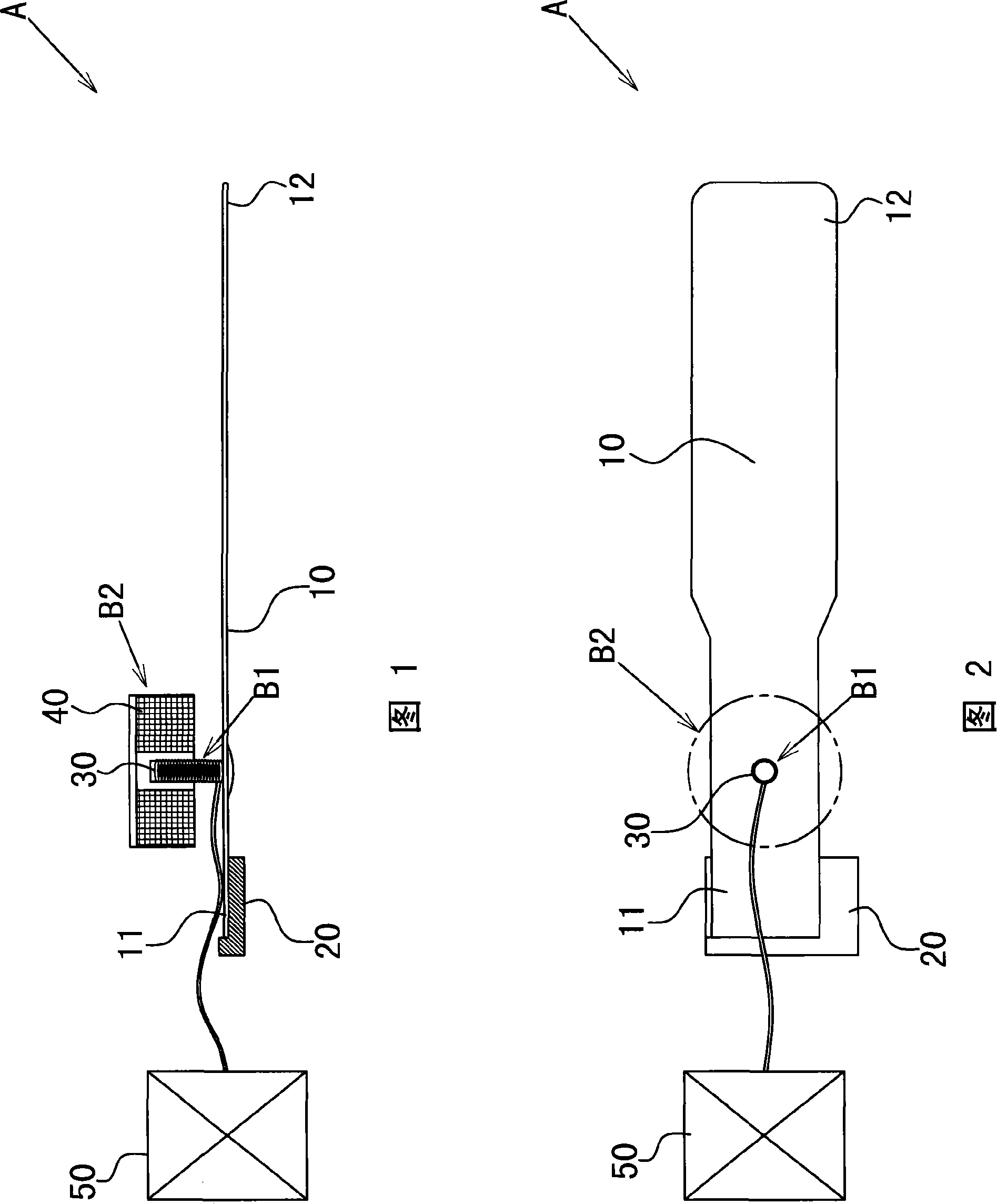
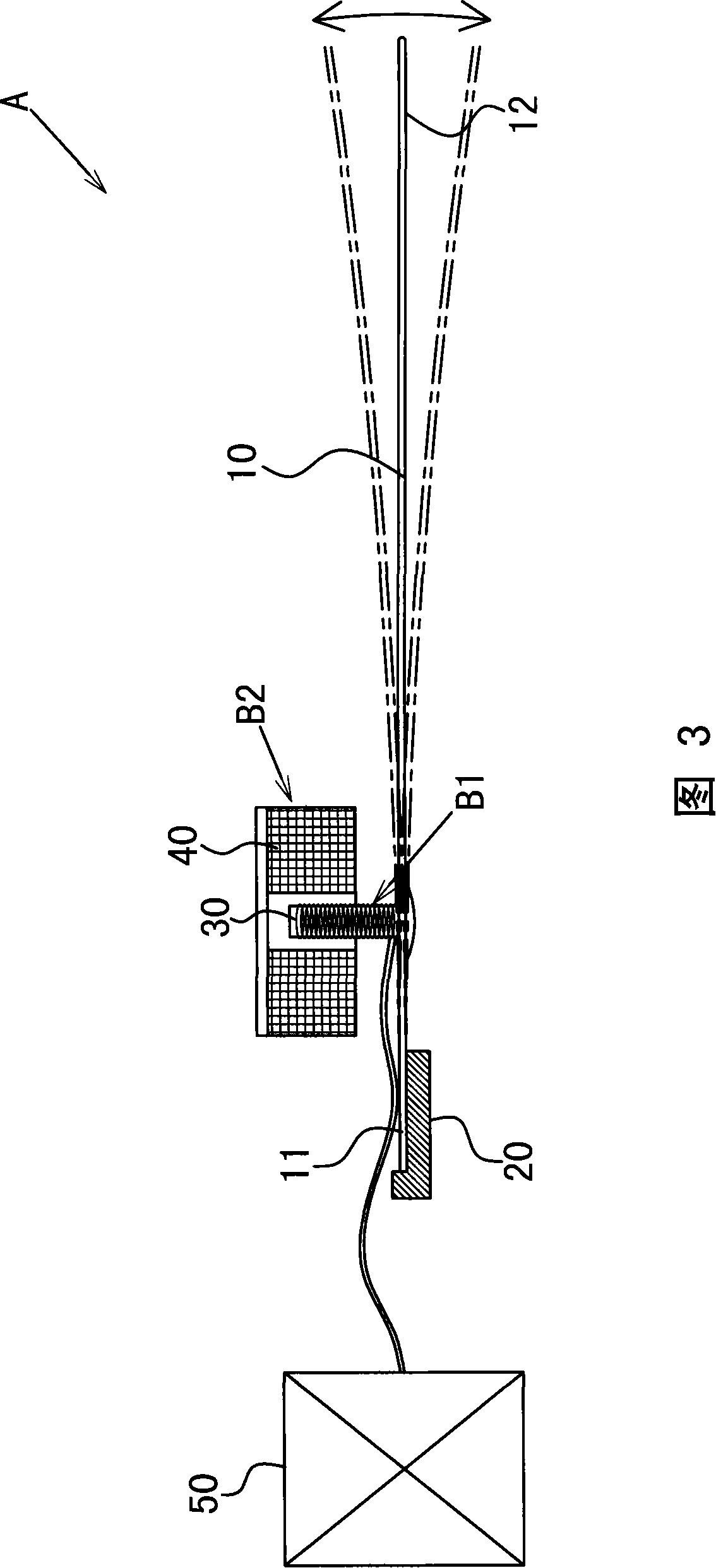
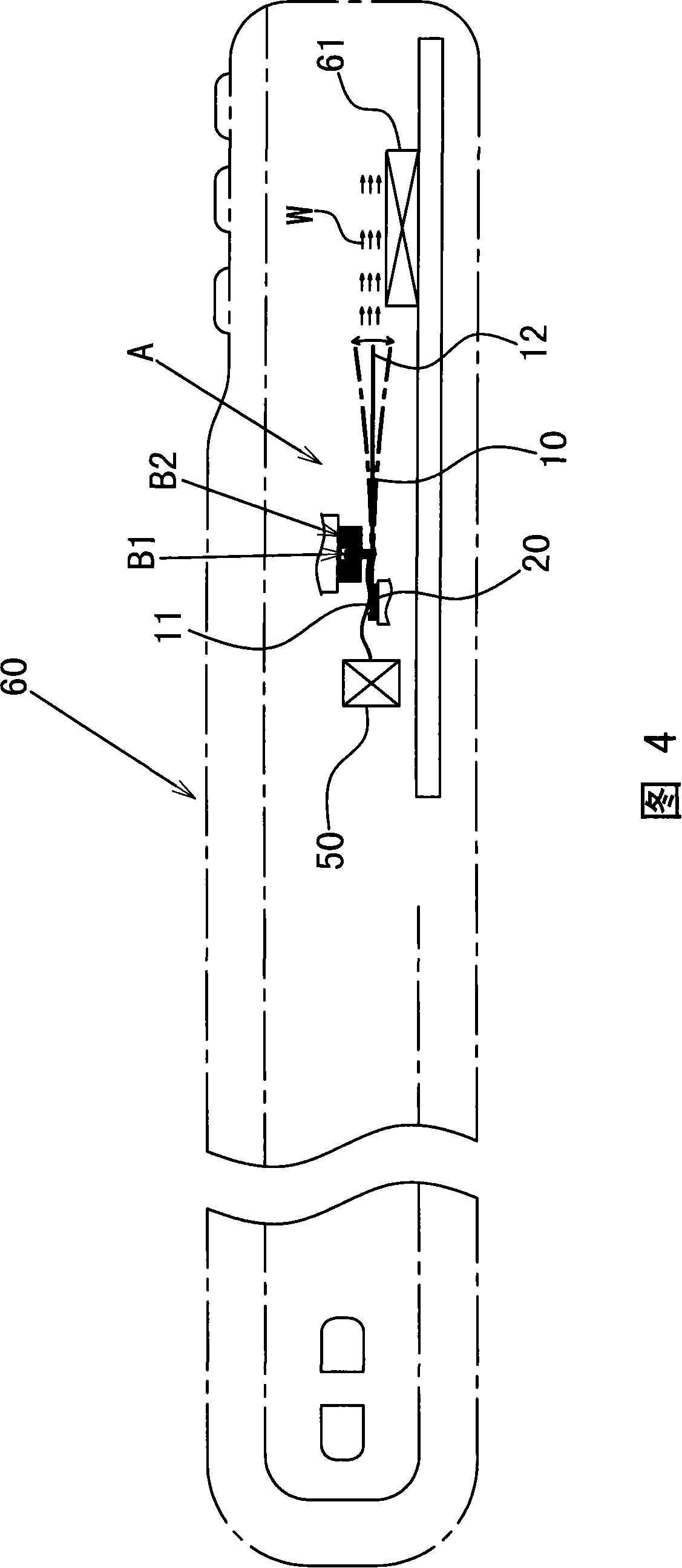
[0029] Please refer to Figures 1-2, which are preferred embodiments of the airflow generator of the present invention, the airflow generator A includes:

[0030] The sheet body 10 is in the shape of a long plate, including a support portion 11 and a swing end 12 away from the support portion 11;

[0031] The first magnetic induction part B1 is assembled at the position of the sheet body 10 close to the supporting part 11;

[0032] The second magnetic induction action part B2 is assembled at the corresponding interval of the first magnetic induction action part B1, so the magnetic induction state between the first and second magnetic induction action parts B1 and B2 can be used Changes, resulting in repeated changes of magnetic attraction and repulsion, and then can drive the swing end 12 of the sheet body 10 to swing.

[0033] Wherein, the support portion 11 of the sheet body 10 is combined with a fixed seat 20;

[0034] The support portion 11 and the fixing seat 20 are fixe...


PUM


Abstract

The invention provides an airflow generator, which is better provided with a sheet-shaped body; the sheet-shaped body comprises a support section and a swinging end, the sheet-shaped body near the support section is provided with a first magnetic induction functioning section which is corresponding to a second magnetic induction functioning section arranged at a spacing location of the sheet-shaped body, thereby the magnetic induction condition changing between the first magnetic induction functioning section and the second magnetic induction functioning section can result to the repetitive change of magnetism suction and exclusion, thereby the swinging end of the sheet-shaped body can be driven to swing; the volume of the novel structure of airflow generator can reach a tiny flat condition with an effective air-driving heat radiating effect; therefore, the invention can solve the problem in the prior radiator fan, which is widely used in the heat radiating structure of different light and small models of electronic equipment.

Description

technical field [0001] The invention relates to an airflow generator, in particular to an innovative design which utilizes the principle of electromagnetic induction to drive a sheet-shaped body to swing, thereby generating wind-driven airflow, so that it can be applied to the field of heat dissipation structures. Background technique [0002] When electronic equipment is in operation, it will generate different degrees of heat according to the scale and capacity of its operation. At present, it is generally used in the heat dissipation structure of electronic equipment, and it is a cooling fan. The development trend of thinner and lighter communication equipment must also be reduced. [0003] However, since the overall necessary components of the cooling fan are composed of a rotor, a stator, and an annular fan blade, its volume is always limited by its cylindrical space shape and it is difficult to further flatten it. Moreover, its annular When the column fan blade is red...

Claims


Application Information

Patent Timeline
Patent Type & Authority Applications(China)
IPC IPC(8): F04D33/00
Inventor 饶振奇周德樟张良升
Owner SUZHOU FORCECON ELECTRIC
Why Eureka
Try Eureka