High-safety photovoltaic module-level fire safety switch

A high-safety, safety switch technology, applied in the field of photovoltaic systems, can solve the problems of affecting the service life of the equipment, consuming a lot of time and energy, and difficult to dissipate heat, so as to facilitate the removal or installation of cover plates, improve service life, and improve work. The effect of efficiency

Pending Publication Date: 2021-03-19
SUZHOU PROJOY NEW ENERGY EQUIP
View PDF5 Cites 2 Cited by
  • Summary
  • Abstract
  • Description
  • Claims
  • Application Information

AI Technical Summary

Problems solved by technology

[0004] Aiming at the deficiencies of the prior art, the present invention provides a high-safety component-level fire safety switch for photovoltaics, which has the advantages of high-efficiency heat dissipation function and fast clamping and fixing function, and solves the practical problems of existing fire safety switches. In the process, because the shell and the upper cover are fixedly connected by screws, the internal equipment of the fire switch is directly in a sealed environment. During the use of the fire switch, the internal equipment will generate a certain amount of heat, and the heat in the sealed state It is difficult to dissipate, and it is exposed to high temperature for a long time, which seriously affects the service life of the equipment. At the same time, when there is a failure inside the fire switch, the maintenance personnel need to remove the upper cover of the fire switch, but the screws need to be spent in the process of installation and disassembly. It takes a lot of time and energy, and the screws need to be properly preserved after disassembly to avoid loss, which leads to further optimization of this installation method

Method used


Image

  • High-safety photovoltaic module-level fire safety switch
  • High-safety photovoltaic module-level fire safety switch
  • High-safety photovoltaic module-level fire safety switch

Examples


Embodiment Construction

[0026] The following will clearly and completely describe the technical solutions in the embodiments of the present invention with reference to the accompanying drawings in the embodiments of the present invention. Obviously, the described embodiments are only some, not all, embodiments of the present invention. Based on the embodiments of the present invention, all other embodiments obtained by persons of ordinary skill in the art without making creative efforts belong to the protection scope of the present invention.

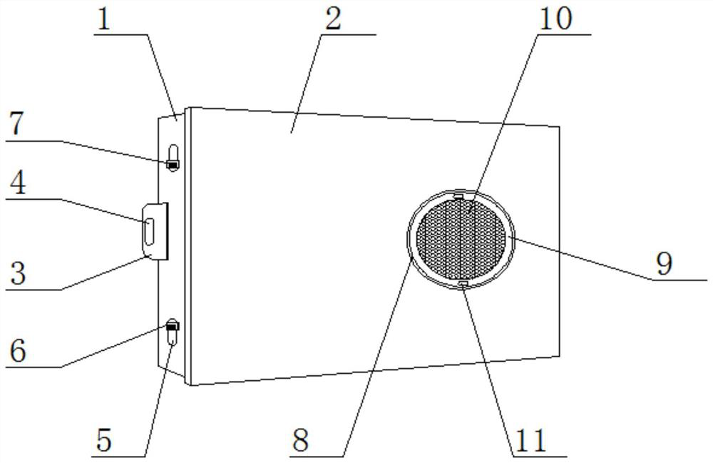
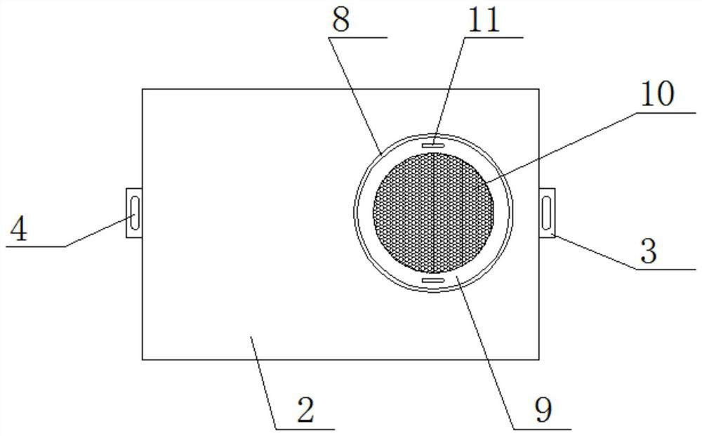
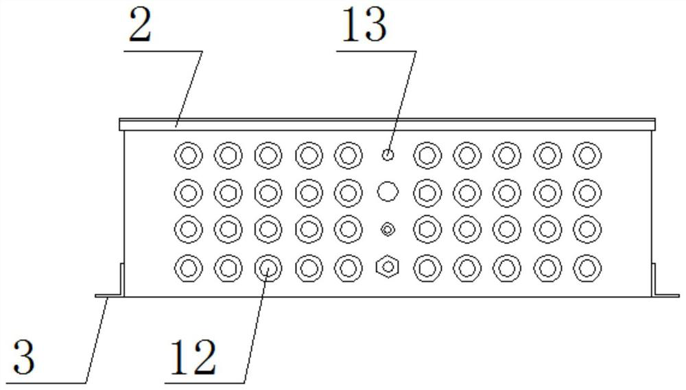
[0027] see Figure 1-8, a high-safety module-level fire safety switch for photovoltaics, including a housing 1, mounting parts 3 are welded on both sides of the housing 1, and grooves 4 are opened on the surface of the mounting parts 3, which can facilitate bolts to pass through The present invention is fixedly installed through the groove 4, and multiple sets of cable joints 12 are installed on the front of the housing 1, and the surface of the housing 1 is p...


PUM


Abstract

The invention relates to the technical field of photovoltaic systems, and discloses a high-safety photovoltaic module-level fire safety switch which comprises a shell, limiting pieces are installed insliding rails through sliding blocks, one side of each limiting piece is connected with the inner side of the shell through a second reset spring. A micro motor, a switch and a temperature sensor areinstalled on the surface of the circuit board, electronic cooling fins are installed on the surface of the circuit board, a small cooling fan is installed at the top of the installation frame, clamping blocks are arranged on the two sides of the first fixing block, and a filter screen is arranged in the middle of the installation frame. According to the high-safety photovoltaic module-level firesafety switch, by arranging the electronic cooling fin, the small cooling fan, the filter screen, the clamping block and the limiting block, the high-safety photovoltaic module-level fire safety switch has an efficient cooling function and a rapid clamping and fixing function, the filter screen and the cover plate are convenient to disassemble and assemble, the surface of the filter screen is keptclean, and the cooling effect is improved.

Description

technical field [0001] The invention relates to the technical field of photovoltaic systems, in particular to a high-safety component-level fire safety switch for photovoltaics. Background technique [0002] Photovoltaic modules generally refer to solar cell modules. In most photovoltaic systems, the DC isolation switch is integrated in the inverter. After the DC switch is turned off, the cables connected to the solar modules still have a direct current of up to 600-1000 volts. In the event of a fire, firefighters are exposed to very serious potential hazards. Before extinguishing the fire, the firefighters first turn off the AC power; at this time, the fire safety switch collects the signal of the grid power failure, and if the power failure time exceeds 5s, it will automatically disconnect the isolation switch. Because the fast shutdown is close to the photovoltaic module, it also directly disconnects the DC current, creating a safe fire fighting environment for firefigh...

Claims


Application Information

Patent Timeline
Patent Type & Authority Applications(China)
IPC IPC(8): H01H9/52H01H9/04H01H9/02
CPCH01H9/52H01H9/047H01H9/04H01H9/0271H01H9/02
Inventor 何美玲刘克法张世超
Owner SUZHOU PROJOY NEW ENERGY EQUIP
Why Eureka
Try Eureka