
Lens module and camera module group

A lens module and lens barrel technology, applied in the field of photography, can solve the problems of large space, driving motor occupation, large volume of lens modules and camera modules, etc.

Inactive Publication Date: 2010-09-29
HONG FU JIN PRECISION IND (SHENZHEN) CO LTD +1
View PDF3 Cites 0 Cited by
  • Summary
  • Abstract
  • Description
  • Claims
  • Application Information

AI Technical Summary

Problems solved by technology

[0004] However, the drive motor often takes up a lot of space, resulting in the large size and complex structure of the lens module and camera module that use the drive motor to drive the focus, which cannot meet the needs of light, thin and small.

Method used


Image

  • Lens module and camera module group
  • Lens module and camera module group
  • Lens module and camera module group

Examples


Embodiment Construction

[0011] The present invention will be further described in detail below in conjunction with the accompanying drawings.

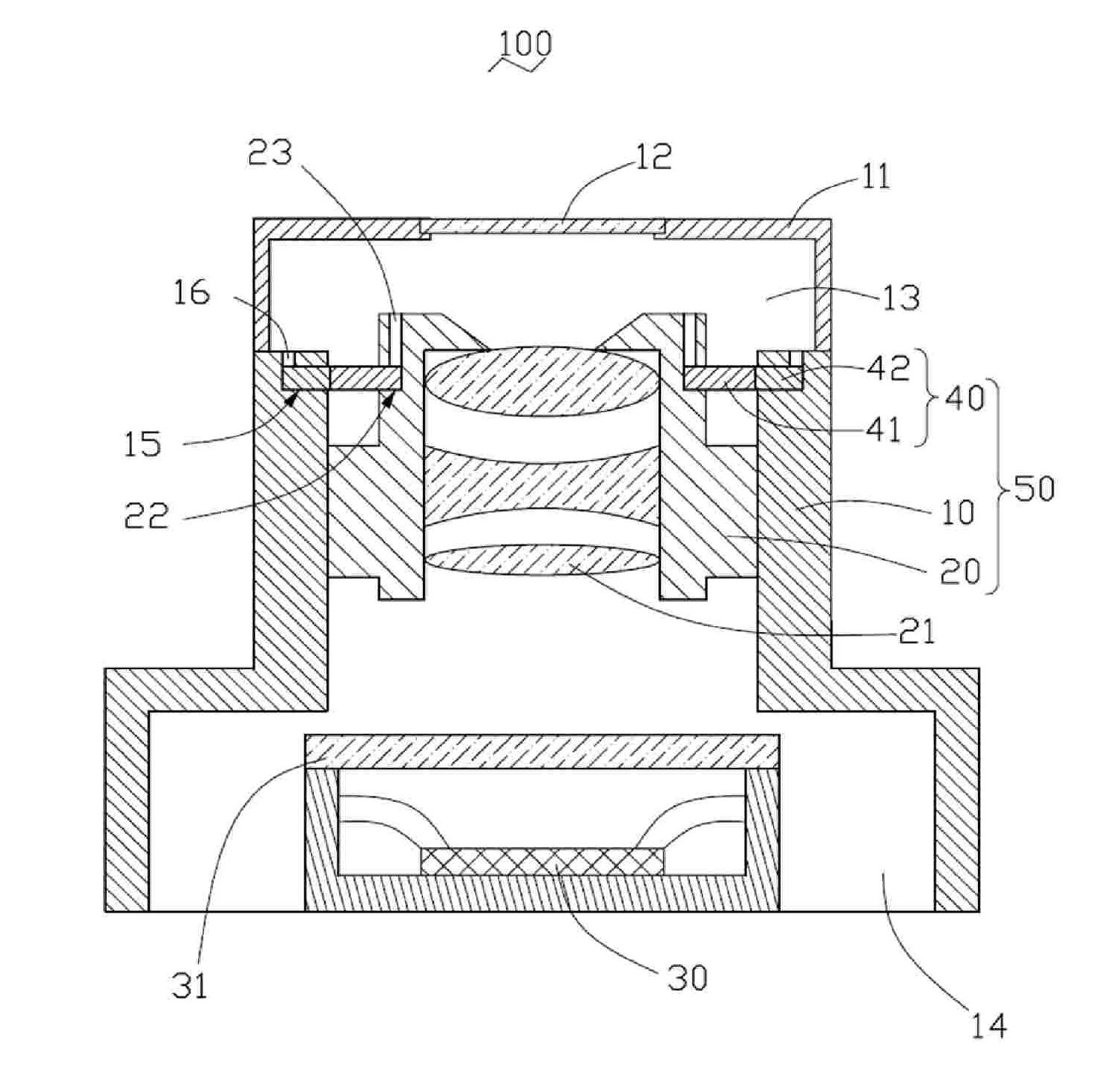
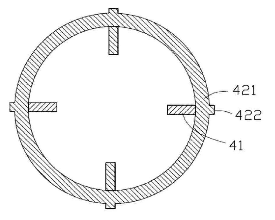
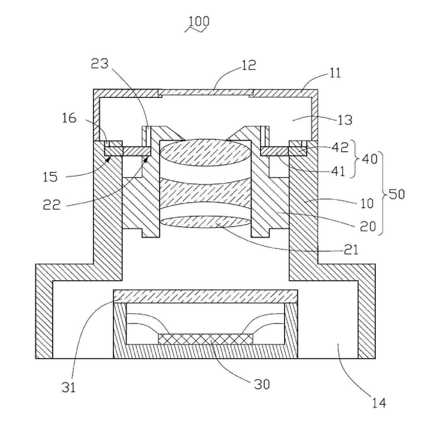
[0012] see figure 1 , is a camera module 100 provided by an embodiment of the present invention, which includes a base 10 , a lens barrel 20 , a plurality of driving arms 40 and an image sensor 30 . Wherein the base 10 , a lens barrel 20 and a plurality of driving arms 40 form a lens module 50 .

[0013] The base 10 has a top accommodating cavity 13 and a bottom accommodating cavity 14 which communicate with each other, and are respectively used to accommodate the lens barrel 20 and the image sensor 30, and make the lens barrel 20 and the image sensor 30 pair I am setting. Preferably, a protective cover 11 is provided on the top of the base 10 for preventing dust and other sundries from entering the base 10 and contaminating the optical components in the base 10 . The part of the protective cover 11 facing the lens barrel 20 is made of transparent material...


PUM


Abstract

The present invention provides a lens module comprising a base, a lens cone and a plurality of driving arms. The base is provided with a top holding chamber for holding the lens cone which is provided with at least a lens. One end of the driving arm is fixed on the other end of the lens cone and is fixed on the base; the driving arm comprises a flexible section with piezoelectric material; through exerting voltage on the piezoelectric material, the flexible section can be bent to drive the lens cone move along the direction of optical axis. The lens module avoids adopting drive motors and other structures, thereby simplifying the whole structure and reducing the whole size.

Description

technical field [0001] The invention relates to the field of photography, in particular to a lens module and a camera module using the lens module. Background technique [0002] With the development of camera technology, camera modules are widely used in camera devices for various purposes. The combination of camera modules and various portable electronic devices such as mobile phones, video cameras, computers, etc. is favored by many consumers. . [0003] The camera module usually includes a driving motor, at least one lens module driven by the driving motor, and a photosensitive component arranged opposite to the lens module. The lens module may include one or more lenses, the lenses are arranged opposite to the photosensitive component, and the center point of the photosensitive component is located on the optical axis of the one or more lenses. When focusing, use the driving motor to drive the relative displacement of the lens group and the photosensitive component to ...

Claims


Application Information

Patent Timeline
Patent Type & Authority Patents(China)
IPC IPC(8): G02B7/02
CPCG02B7/102G02B13/001G02B15/173G03B13/36
Inventor 张仁淙
Owner HONG FU JIN PRECISION IND (SHENZHEN) CO LTD
Learn More