Dot matrix zoom mechanism and zoom method

A zoom mechanism and dot-matrix technology, applied to point light sources, lighting devices, light sources, etc., can solve the problems of inability to zoom with zoom mirrors, slow focusing speed, complex zoom structure, etc., and achieve fast overall zoom and fast overall adjustment The effect of simple structure of focus and zoom mechanism

Inactive Publication Date: 2014-04-23
GUANGZHOU YAJIANG PHOTOELECTRIC EQUIP CO LTD
View PDF7 Cites 0 Cited by
  • Summary
  • Abstract
  • Description
  • Claims
  • Application Information

AI Technical Summary

Problems solved by technology

But the existing zooming structure is relatively complicated, and the zooming is not fast. For example, a variable-focusing LED lamp is disclosed in the patent document whose application number is 200810142645.3 and the publication date is December 31, 2008, and specifically discloses that the LED lamp includes Rear seat, LED with substrate, lamp body, lens, limit screw, lens bracket, adjustment ring, lamp body includes front lamp body and rear lamp body, LED with substrate is fixed on the rear seat, the head of the rear lamp body , the tail part are fixedly connected with the tail part and the rear seat of the front lamp body respectively, the lens is fixed on the lens bracket, the adjusting ring is fixed and rotated in the axial direction with the front lamp body, and the side wall of the lens bracket is provided with a guide Groove, external thread, internal thread is provided on the adjusting ring, the external thread and the internal thread are matched and connected, the limit screw is fixed on the rear seat and protrudes from the side wall of the rear seat, and the limit screw is matched with the guide groove ; When the adjusting ring is rotated, the distance between the lens and the LED can be adjusted, so as to achieve the purpose of focusing, but the structure of the LED lamp is complicated, and the speed of focusing is slow
[0003] In addition, there is another way to adjust the lens board through a motor, that is, install a motor on the lamp bead board, install a screw on the output of the motor, and install a nut on the lens board. When the motor is working, the function of the screw and the nut It can drive the lens plate to move up and down, so as to achieve the purpose of focusing, but this structure is still relatively complicated, and the speed of focusing is slow; in addition, this structure cannot zoom in on the zoom lens corresponding to each lamp bead, so it is difficult to obtain special effect spot

Method used


Image

  • Dot matrix zoom mechanism and zoom method
  • Dot matrix zoom mechanism and zoom method
  • Dot matrix zoom mechanism and zoom method

Examples


Embodiment Construction

[0012] The present invention will be further described in detail below in conjunction with the accompanying drawings and specific embodiments.

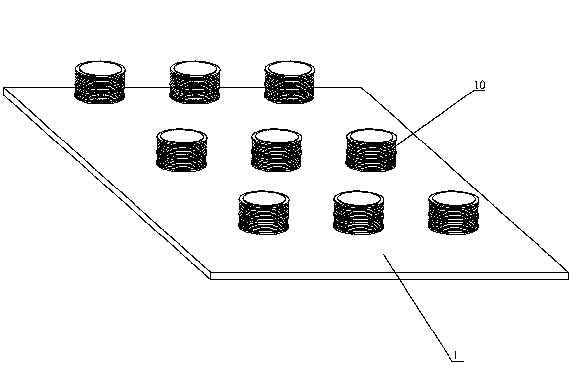
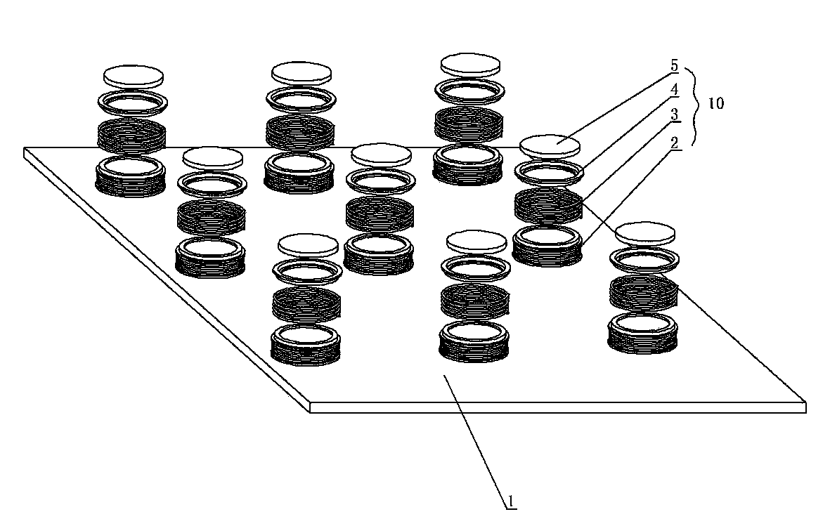
[0013] Such as figure 1 and figure 2 As shown, the dot matrix zoom mechanism includes a lamp bead board 1 and more than two zoom devices 10, and the zoom devices 10 are arranged in a dot matrix on the lamp bead board. The zoom device 10 includes an electromagnet 2 , a lamp bead, a spring 3 , a magnetic lens seat 4 and a lens group 5 .

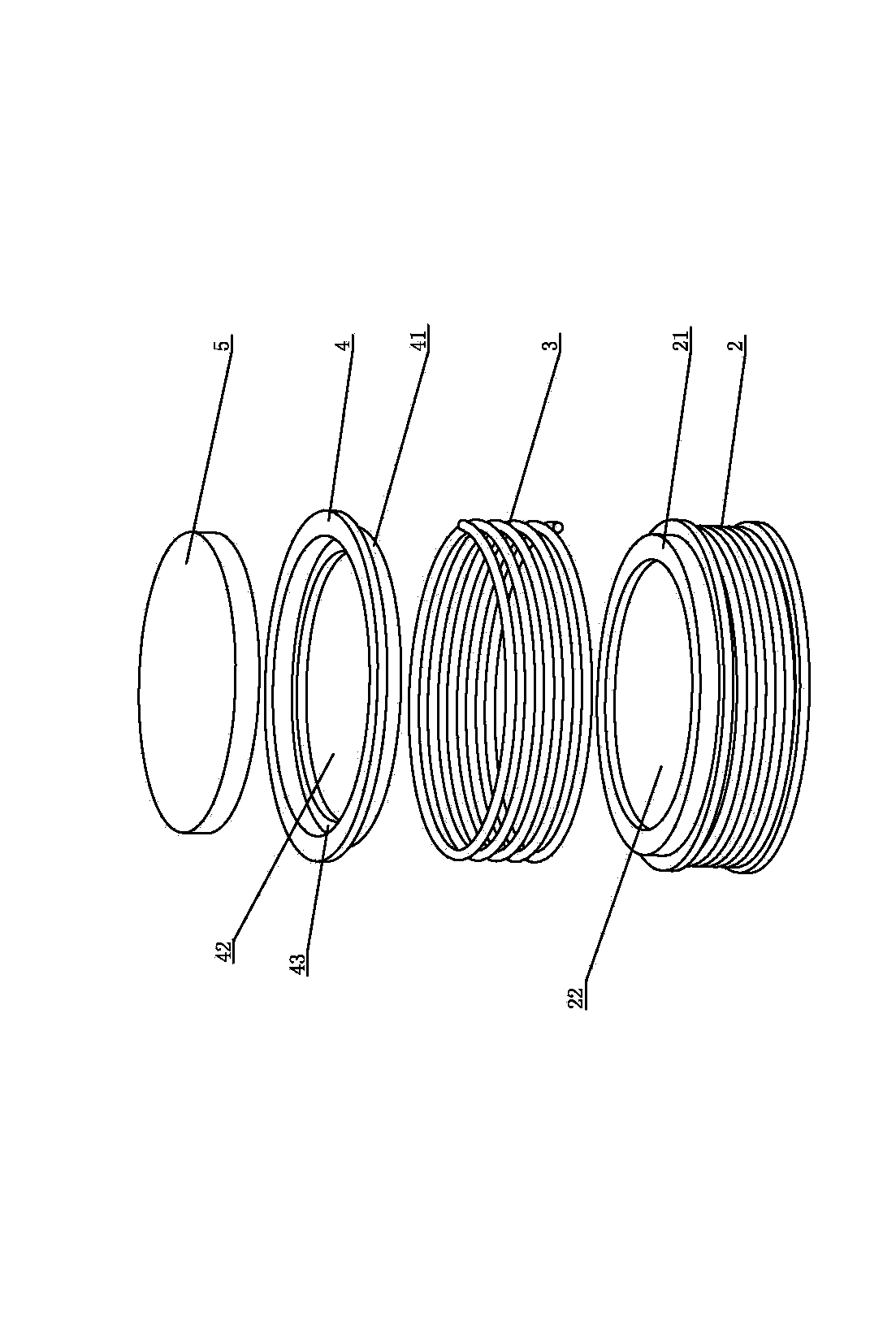
[0014] Such as figure 1 and figure 2 As shown, the lower end of the electromagnet 2 is welded on the lamp bead board 1 . Such as image 3 As shown, the upper end of the electromagnet 2 has a first positioning post 21 , and the electromagnet 2 has a light hole 22 . A lamp bead installed on the lamp bead board 1 is correspondingly provided in each light through hole. The lower end of the magnetic lens has a second positioning post 41, the spring 3 is arranged between the magnetic lens seat 4 and...


PUM


Abstract

The invention discloses a dot matrix zoom mechanism and a zoom method. The zoom mechanism comprises a lamp bead plate, two or more zoom devices are arranged on the lamp bead plate, each zoom device comprises an electromagnet, a spring, a magnetic lens base and a lens set, the electromagnets are installed on the lamp bead plate and provided with light passing holes, one lamp bead installed on the lamp bead plate is correspondingly arranged in each light passing hole, each spring is arranged between the corresponding magnetic lens base and the corresponding electromagnet, each magnetic lens is provided with a light hole, and each lens set is arranged on the corresponding magnetic lens base. According to the zoom method, overall and independent motion of the magnetic lens bases is achieved by controlling the electromagnets, so that the purposes of overall zoom and independent zoom are achieved. Therefore, the zoom mechanism of the structure is simple, and can achieve rapid zoom and obtain light spots with special effects.

Description

technical field [0001] The invention relates to a zoom mechanism and a zoom method in a lamp. Background technique [0002] In order to adjust the focal point of the light, adjust the size and brightness of the light spot, it is generally realized by zooming. But the existing zooming structure is relatively complicated, and the zooming is not fast. For example, a variable-focusing LED lamp is disclosed in the patent document whose application number is 200810142645.3 and the publication date is December 31, 2008, and specifically discloses that the LED lamp includes Rear seat, LED with substrate, lamp body, lens, limit screw, lens bracket, adjustment ring, lamp body includes front lamp body and rear lamp body, LED with substrate is fixed on the rear seat, the head of the rear lamp body , the tail part are fixedly connected with the tail part and the rear seat of the front lamp body respectively, the lens is fixed on the lens bracket, the adjusting ring is fixed and rotated ...

Claims


Application Information

Patent Timeline
Patent Type & Authority Applications(China)
IPC IPC(8): F21V14/06F21Y101/02F21Y105/16F21Y115/10
Inventor 陈志勤
Owner GUANGZHOU YAJIANG PHOTOELECTRIC EQUIP CO LTD
Why Eureka
Try Eureka