Projector and projection method

a technology of projection lens and projector body, which is applied in the field of projector and projection method, can solve the problems of increasing the size of the projector body and the manufacturing cost, complicated mechanism, and difficulty in obtaining a projection lens which can meet both requirements, and achieve the effect of preventing the occurrence of trapezoidal distortion

Inactive Publication Date: 2006-12-21
SEIKO EPSON CORP
View PDF7 Cites 24 Cited by
  • Summary
  • Abstract
  • Description
  • Claims
  • Application Information

AI Technical Summary

Benefits of technology

[0010] An advantage of some aspects of the invention is to provide a projector with a relatively compact and low-cost projection lens, which enables foc...

Problems solved by technology

Hence, in order to achieve brightness equivalent to brightness in the case without doing the lens shift, it is necessary to make the diameter of the projection lens into sufficient size, which tends to increase the size of the projector body and a manufacturing cost there...

Method used


Image

  • Projector and projection method
  • Projector and projection method
  • Projector and projection method

Examples


first embodiment

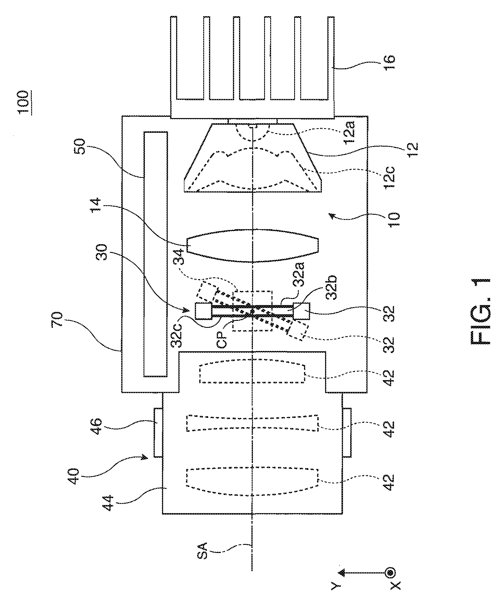
[0024]FIG. 1 is a exploded perspective view of assistance in explaining a structure of a projector in association with the first embodiment. The projector 100 in the embodiment includes: an illuminating device 10; a light-modulation device 30; a projection optical system 40; and a circuit unit 50. Of these constituents, optical elements constituting the illuminating device 10, the light-modulation device 30 and the projection optical system 40 respectively are positioned and housed in a housing part 70, which is a housing for optical parts and for which a predetermined system optical axis SA is set.

[0025] The illuminating device 10 is fixed so that it is embedded in the rectangular parallelepiped housing part 70, and includes: an illuminating unit 12 including a light-emitting source; an extension lens 14 for beam shaping; and a cooling fin 16 as a heat-dissipating device. Of these constituents, the illuminating unit 12 has: an LED light source 12a which creates a source light with...

second embodiment

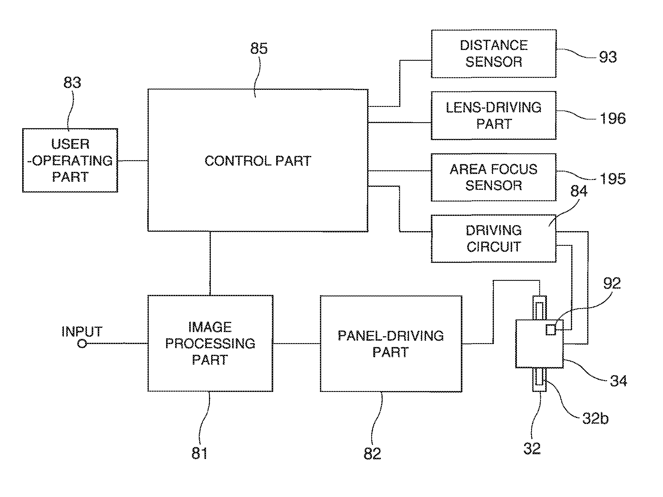
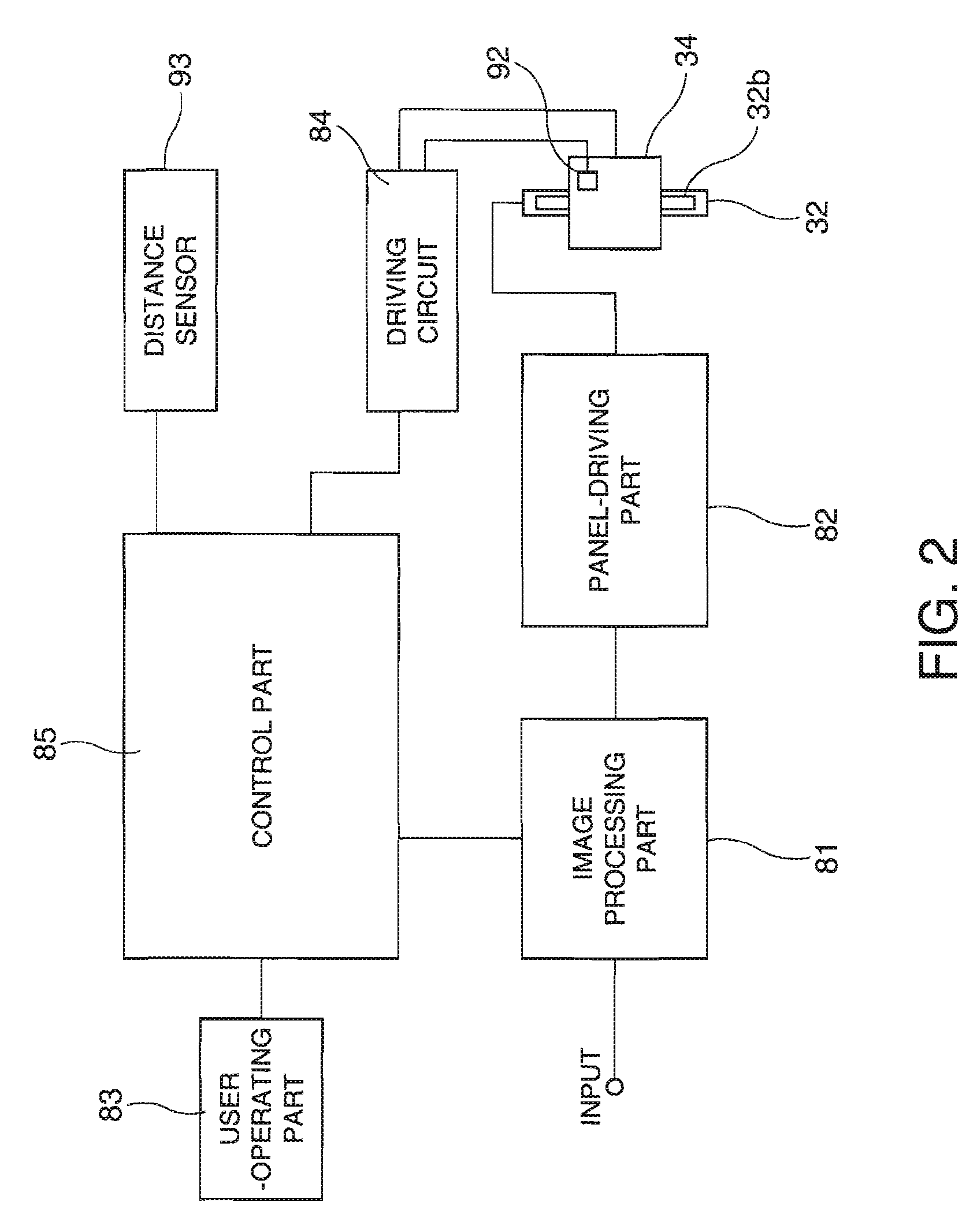
[0047]FIG. 5 is a block diagram of assistance in partially conceptualizing a projector in association with the second embodiment. The projector of the second embodiment is a modification of the projector of the first embodiment, and therefore common parts are identified by the same reference character, and repeated description thereof are omitted. Further, in a portion which is not described particularly, the projector of the second embodiment shall have the same structure as that of the projector of the first embodiment.

[0048] The circuit device included in the projector of the second embodiment further includes an area focus sensor 195 and a lens-driving part 196. The area focus sensor 195 is arranged so that it can detect an in focus condition in a center portion, an upper portion and a lower portion of an image projected on the screen SC. In addition, the lens-driving part 196 can force the focusing ring 46 to work by rote and automatically adjust the focus condition of the pro...


PUM


Abstract

A projector includes: a light-modulation device for modulating an illumination light according to a piece of image information; a projection optical system for protecting a modulated light resulting from the modulation by the light-modulation device as an image on a screen; a movable holder capable of holding the light-modulation device in a condition where the light-modulation device is tilted with respect to an optical axis; and a control-processing device which corrects a projected image formed in the light-modulation device based on a distance from the projection optical system to the screen and a tilt angle of the light-modulation device thereby to correct a trapezoidal distortion of an image projected on the screen when the light-modulation device is arranged in relation to the projection optical system and the screen so that a requirement of Scheimpflug rule is satisfied.

Description

BACKGROUND [0001] 1. Technical Field [0002] The present invention relates to a projector which uses a liquid crystal display panel or some other light-modulation device to project a video image, and a projection method using the same. [0003] 2. Related Art [0004] A projector is typically placed on a desk, and used to project an image on a screen vertically placed above the desk. In this case, the projector body is placed horizontally, and oblique projection is performed by lens shift to prevent trapezoidal distortion, focus blurring, etc. [0005] However, in the case of using means of lens shift, the optical system of the projector is arranged so that the optical axis of a light valve thereof is displaced from the optical axis of a projection lens thereof. Hence, in order to achieve brightness equivalent to brightness in the case without doing the lens shift, it is necessary to make the diameter of the projection lens into sufficient size, which tends to increase the size of the proj...

Claims


Application Information

Patent Timeline
IPC IPC(8): G03B21/14
CPCG03B21/14H04N9/3194H04N9/3185G03B21/16G03B21/147
Inventor KURIHARA, TORU
Owner SEIKO EPSON CORP
Why Eureka
Try Eureka