
Image display driving method for LCD device

A liquid crystal display device and image display technology, which is applied to static indicators, instruments, etc., can solve the problems of inappropriateness and inability to completely improve the blurring phenomenon, and achieve the effect of reducing power supply and improving the blurring phenomenon.

Inactive Publication Date: 2008-04-02
GIGNO TECH CO LTD
View PDF0 Cites 2 Cited by
  • Summary
  • Abstract
  • Description
  • Claims
  • Application Information

AI Technical Summary

Problems solved by technology

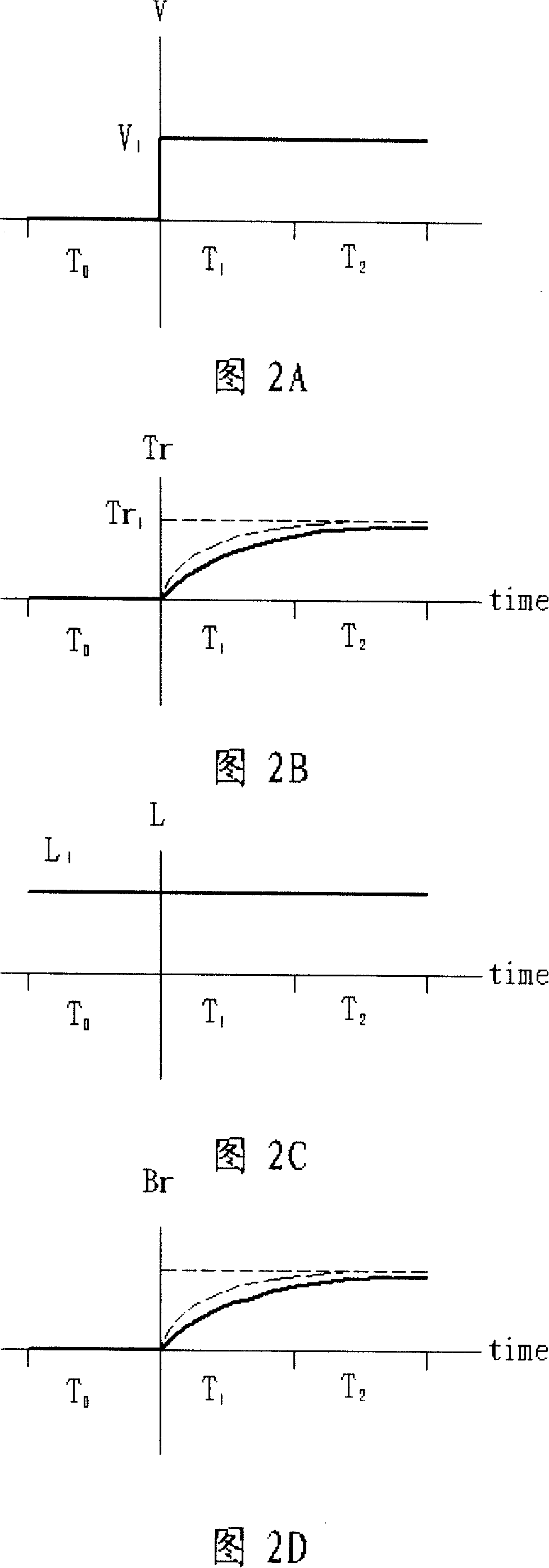
[0008] It can be seen that the image display driving method of the above-mentioned existing liquid crystal display device cannot completely improve the blur phenomenon no matter whether it is to use a fast-response liquid crystal, to use an over-excitation drive technology, or to add an intermittent driving backlight module technology.
In order to solve the above-mentioned problems, the relevant manufacturers have tried their best to find a solution, but no suitable design has been developed for a long time, and the general method has no suitable method to solve the above-mentioned problems. This is obviously related. The problem that the industry is eager to solve

Method used


Image

  • Image display driving method for LCD device
  • Image display driving method for LCD device
  • Image display driving method for LCD device

Examples


Embodiment Construction

[0075] In order to further explain the technical means and effects that the present invention adopts to achieve the intended purpose of the invention, below in conjunction with the accompanying drawings and preferred embodiments, the specific implementation methods, methods, Steps, features and effects thereof are described in detail below.

[0076] Please refer to FIG. 5, which is an image display driving method for a liquid crystal display device of the present embodiment, and is applied to a liquid crystal display device 50. This liquid crystal display device 50 includes a liquid crystal display panel 60 and a backlight module. group 70 , and the backlight module 70 is disposed on one side of the liquid crystal display panel 60 . In addition, the liquid crystal display device 50 of this embodiment is not limited, and may be a liquid crystal television or a general display in practice.

[0077] The liquid crystal display panel 60 has a display surface 61 and a plurality of ...


PUM


Abstract

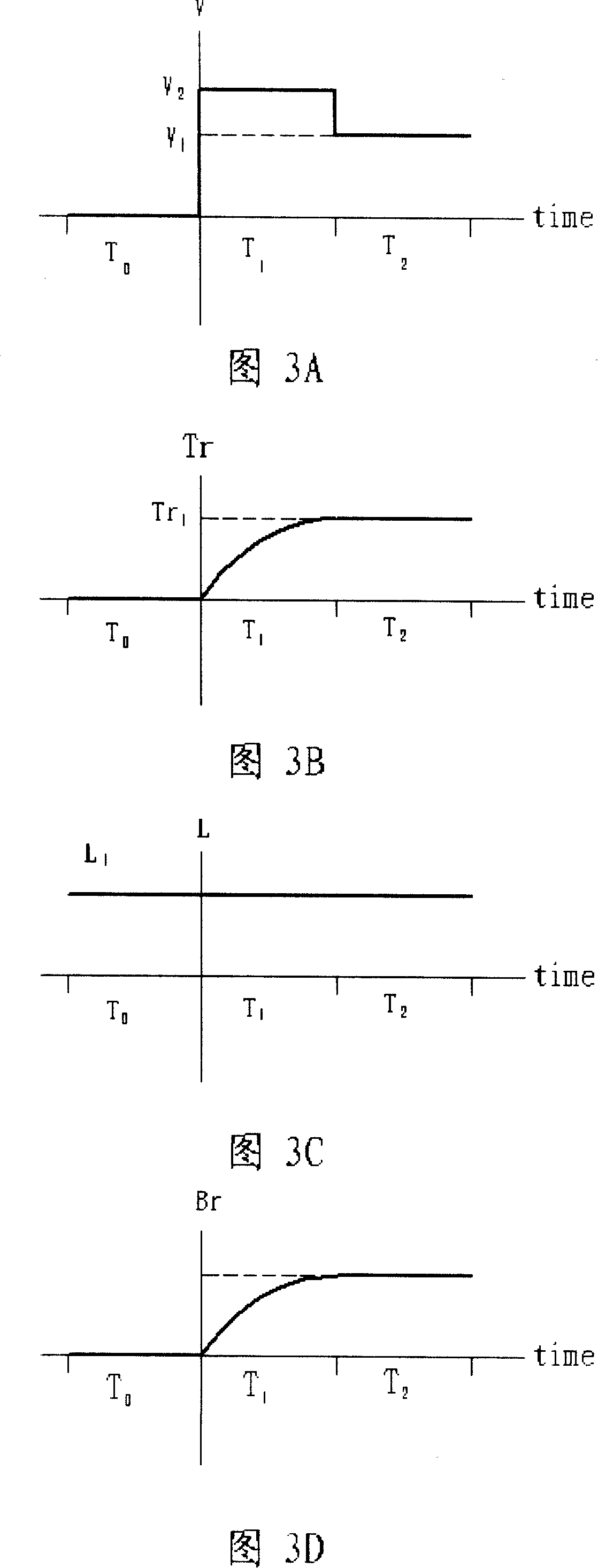
An image display drive method for liquid crystal display unit includes a data conversion program, a display driver and a light source control program, wherein, the data conversion program respectively converts first sub-image picture frame data and second sub-image picture frame data into a prepositive voltage signal and a postpositive voltage signal of the first sub-image picture frame data and a prepositive voltage signal and a postpositive voltage signal of the second sub-image picture frame data which are needed to drive a pixel; the display driver reads the prepositive voltage signal and the postpositive voltage signal of the first sub-image picture frame data and the second sub-image picture frame data in the pixel in turn within picture frame time; the light source control program controls the light source brightness of a first luminescence unit so that the first luminescence unit represents a first mean brightness within the corresponding time during which the prepositive voltage signal of the first sub-image picture frame data is written in the pixel and a second mean brightness bigger than the first mean brightness within the corresponding time during which the postpositive voltage signal of the first sub-image picture frame data is written in the pixel.

Description

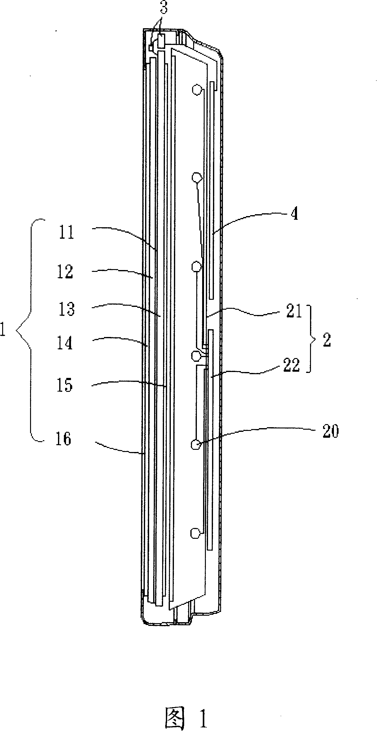
technical field [0001] The present invention relates to an image display driving method of a display device, in particular to an image display driving method of a liquid crystal display device capable of eliminating blurring phenomenon. Background technique [0002] The liquid crystal display device can be roughly divided into a liquid crystal display device used as a general display screen and a liquid crystal display device used as a television in terms of its application. In fact, the basic structures of the two liquid crystal display devices are not very different, but only some components and circuits are different, and some components are arranged in different positions. [0003] As shown in FIG. 1 , an existing liquid crystal display device mainly includes a liquid crystal display panel 1 , a backlight module 2 , a driving circuit 3 , and a control circuit 4 . The liquid crystal display panel 1 at least includes a liquid crystal layer 11 , a color filter substrate 12...

Claims


Application Information

Patent Timeline
Patent Type & Authority Applications(China)
IPC IPC(8): G09G3/36G09G3/20G02F1/133
Inventor 林峰立
Owner GIGNO TECH CO LTD
Learn More