Al technical title is built by PatSnap Al team. It summarizes the technical point description of the patent document.
A camera and weight technology, applied in motor vehicles, measuring devices, measuring circuits, etc., can solve the problem of increasing the weight of the system
Inactive Publication Date: 2008-04-09
HONEYWELL INT INC
View PDF8 Cites 5 Cited by
Summary
Abstract
Description
Claims
Application Information
AI Technical Summary
This helps you quickly interpret patents by identifying the three key elements:
Problems solved by technology
Method used
Benefits of technology
Problems solved by technology
However, this may require complex control circuitry to periodically change the camera's orientation, again adding weight to the system
Method used
Image
Click on the blue label to locate the original text in one second.
Reading with bidirectional positioning of images and text.
Examples
Embodiment Construction
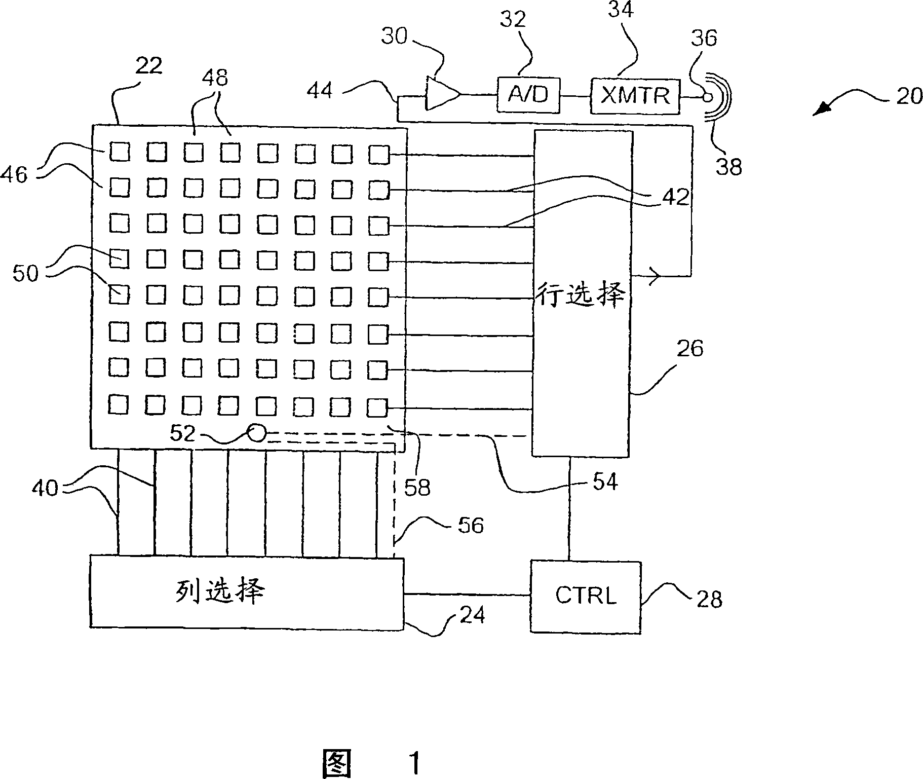
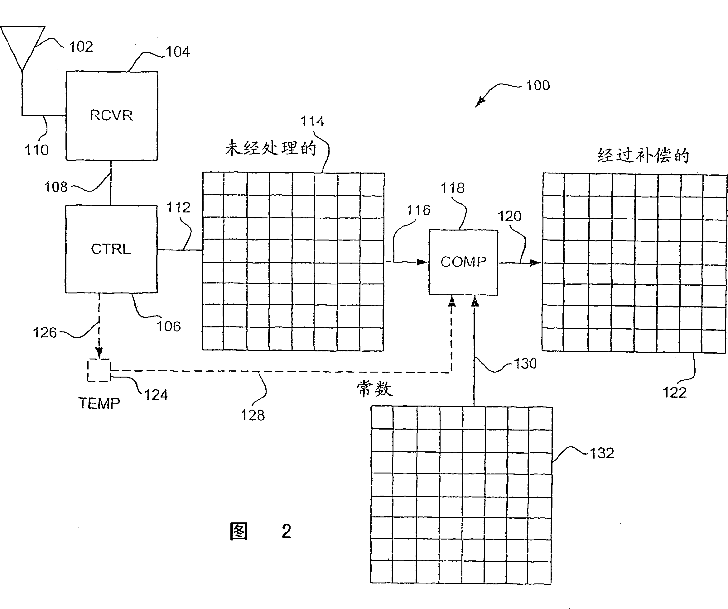
[0027] Figure 1 illustrates a first illustrative infrared camera in accordance with the present invention. In such an embodiment, the infrared camera contains only a detector array for receiving infrared energy, measuring the temperature of the array, and transmitting the unprocessed data to a remote station. An illustrative remote station is shown, for example, in FIG. 2 .
[0028] The infrared camera of FIG. 1 is shown generally at 20 and includes a radiation detector array 22 , a column selector 24 , a row selector 26 , a controller 28 , and optionally a temperature sensor 52 . Radiation detector array 22 includes a plurality of radiation sensing detectors 50 which, in a preferred embodiment, are infrared sensing bolometers. Radiation detectors 50 , in the illustrated embodiment, are positioned in a series of columns 48 , and rows 46 . A controller 28 is provided to control the column selector 24 and the row selector 26 . Controller 28 may contain a counter for moving se...
PUM
Abstract
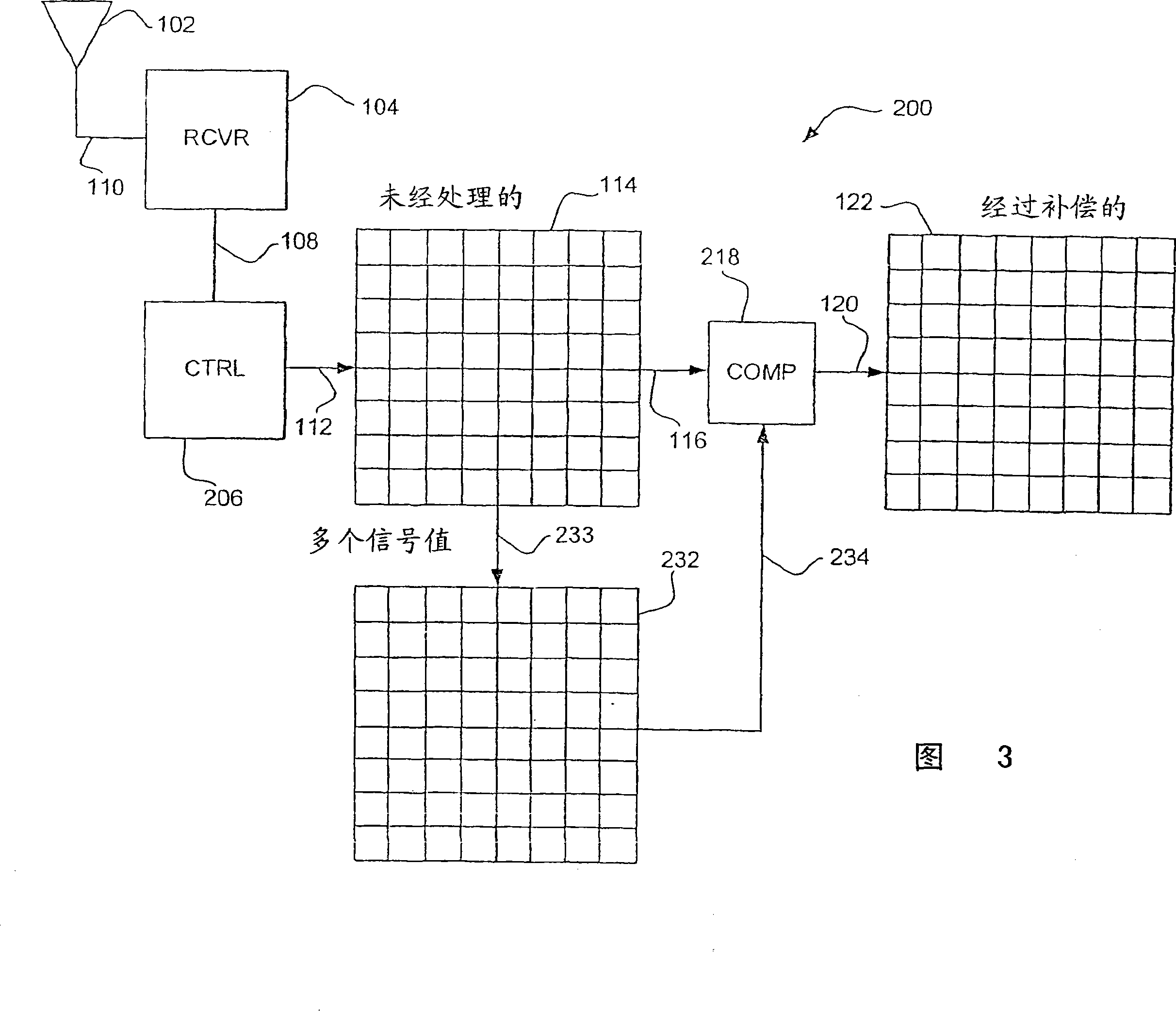
A lightweight camera (20) or detector that does not require a shutter, chopper or thermoelectric stabilizer. Lightweight materials and lightweight packaging techniques are used, and in some embodiments, some or all of the calibration, compensation and processing hardware are moved from the camera (20) itself to a remote station (100). Such a shutterless, lightweight, IR camera, which may operated at ambient temperature, can be mounted on a micro air vehicle (MAV) or the like, with the raw IR sensor data received and processed by a ground station (100).
Description
[0001] This application is a divisional application of: [0002] Application number: 01822869.0 (PCT / US01 / 50077); [0003] Application date: December 20, 2001; [0004] Title of Invention: "Lightweight Infrared Camera". [0005] Cross References to Related Applications [0006] This application is related to U.S. Patent Application Serial No. ___, Field ___, titled "Lenses for Infrared Cameras," and U.S. Patent Application Serial No. ___, Field ___, titled "Operating System for Microbolometers." field of invention [0007] The present invention generally relates to infrared (IR) cameras and detectors. More particularly, the present invention relates to lightweight infrared (IR) cameras and detectors. Background of the invention [0008] Infrared cameras and detectors, and especially microbolometers, are well known to those skilled in the art. See, eg, U.S. Patents 5,688,699, 5,999,211, 5,420,419, and 6,026,337, all of which are incorporated herein by reference. Infrar...
Claims
Application Information
Patent Timeline
Application Date:The date an application was filed.
Publication Date:The date a patent or application was officially published.
First Publication Date:The earliest publication date of a patent with the same application number.
Issue Date:Publication date of the patent grant document.
PCT Entry Date:The Entry date of PCT National Phase.
Estimated Expiry Date:The statutory expiry date of a patent right according to the Patent Law, and it is the longest term of protection that the patent right can achieve without the termination of the patent right due to other reasons(Term extension factor has been taken into account ).
Invalid Date:Actual expiry date is based on effective date or publication date of legal transaction data of invalid patent.
