Power management method, system and equipment
A management method and technology for managing equipment, applied in transmission systems, digital transmission systems, data exchange through path configuration, etc., can solve problems such as bit error rate increase, crosstalk transient sudden change, transmission power increase, etc.
- Summary
- Abstract
- Description
- Claims
- Application Information
AI Technical Summary
Problems solved by technology
Method used
Image
Examples
Embodiment 1
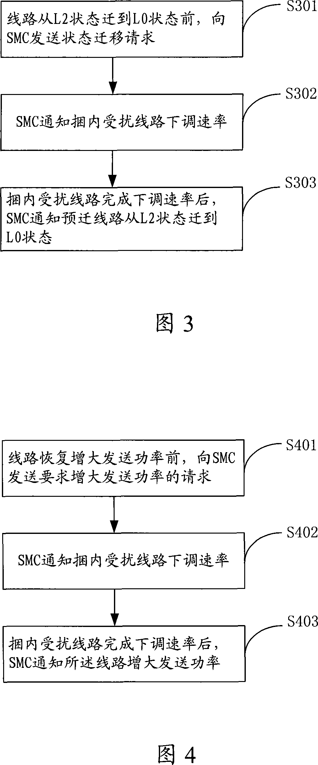
[0030] The embodiment of the present invention provides a method for power management, which can solve the problem of increased crosstalk to adjacent lines when the line transitions from the L2 state to the L0 state. As shown in Figure 3:
[0031] S301: When the data transmission rate on the line decreases, the line transitions from the L0 state to the L2 state, thereby realizing power management; the line that has realized the above power management is now ready to increase the transmission power, that is, the line is ready to be controlled by The L0 state transitions to the L2 state. Before it transitions from the L2 state to the L0 state, the office transceiver unit first sends a state transition request from the L2 state to the L0 state to the SMC.
[0032] S302: The SMC sends an instruction to actively lower the rate to the disturbed lines in the bundle according to the disturbed lines in the bundle that it will affect. The disturbed line in the bundle quickly lowers th...
Embodiment 2
[0038] The difference between the solutions of the second embodiment and the first embodiment is only that the methods for obtaining the down-regulation target rate are different. The specific method is: the central office of each disturbed line in each bundle collects bitmaps for a long time, and establishes a rate influence value model.
[0039] The specific method for establishing the model is: when the line transitions from the L2 state to the L0 state each time, the central office collects the bit map of the disturbed line in the bundle, estimates the impact on the accommodated bits of each subcarrier, and then calculates the disturbed line in the bundle. The rate impact value of the disturbing line. In this way, the down-regulation target rate of the disturbed line can be obtained by subtracting the calculated rate impact value from the current rate of the disturbed line in the bundle.
[0040] Wherein, the collected bit map is collected separately in the L0 state and t...
Embodiment 3
[0043] The difference between the solutions of Embodiment 3 and Embodiments 1 and 2 is also that the methods for obtaining the down-regulation target rate are different.
[0044] The crosstalk effect of the new interfering line on the disturbed line varies with different lines (such as the length of the line, the number of surrounding interfering lines, etc.), and greatly depends on the number of existing interfering sources. For the same line, the received crosstalk is different when there is one interference source and when there are multiple interference sources. When there is one interference source, the crosstalk received by the line is greater than when there are multiple interference sources.
[0045] When a line returns from the L2 state to the L0 state, the SMC knows how many lines are active. Based on this information, the SMC can estimate the amount of Signal to Noise Ratio (SNR) reduction brought by the new interference source to determine the amount of reduction ...
PUM
 Abstract
Description
Claims
Application Information
 - R&D
- Intellectual Property
- Life Sciences
- Materials
- Tech Scout
- Unparalleled Data Quality
- Higher Quality Content
- 60% Fewer Hallucinations
Browse by: Latest US Patents, China's latest patents, Technical Efficacy Thesaurus, Application Domain, Technology Topic, Popular Technical Reports.
© 2025 PatSnap. All rights reserved.Legal|Privacy policy|Modern Slavery Act Transparency Statement|Sitemap|About US| Contact US: help@patsnap.com


