Glass plate conveyance pallet
A glass plate and glass cover technology, which is applied in the direction of conveyor objects, containers, trolleys, etc., can solve problems such as breakage, easy bending of the central part, and positional deviation of the glass plate
- Summary
- Abstract
- Description
- Claims
- Application Information
AI Technical Summary
Problems solved by technology
Method used
Image
Examples
Embodiment 1
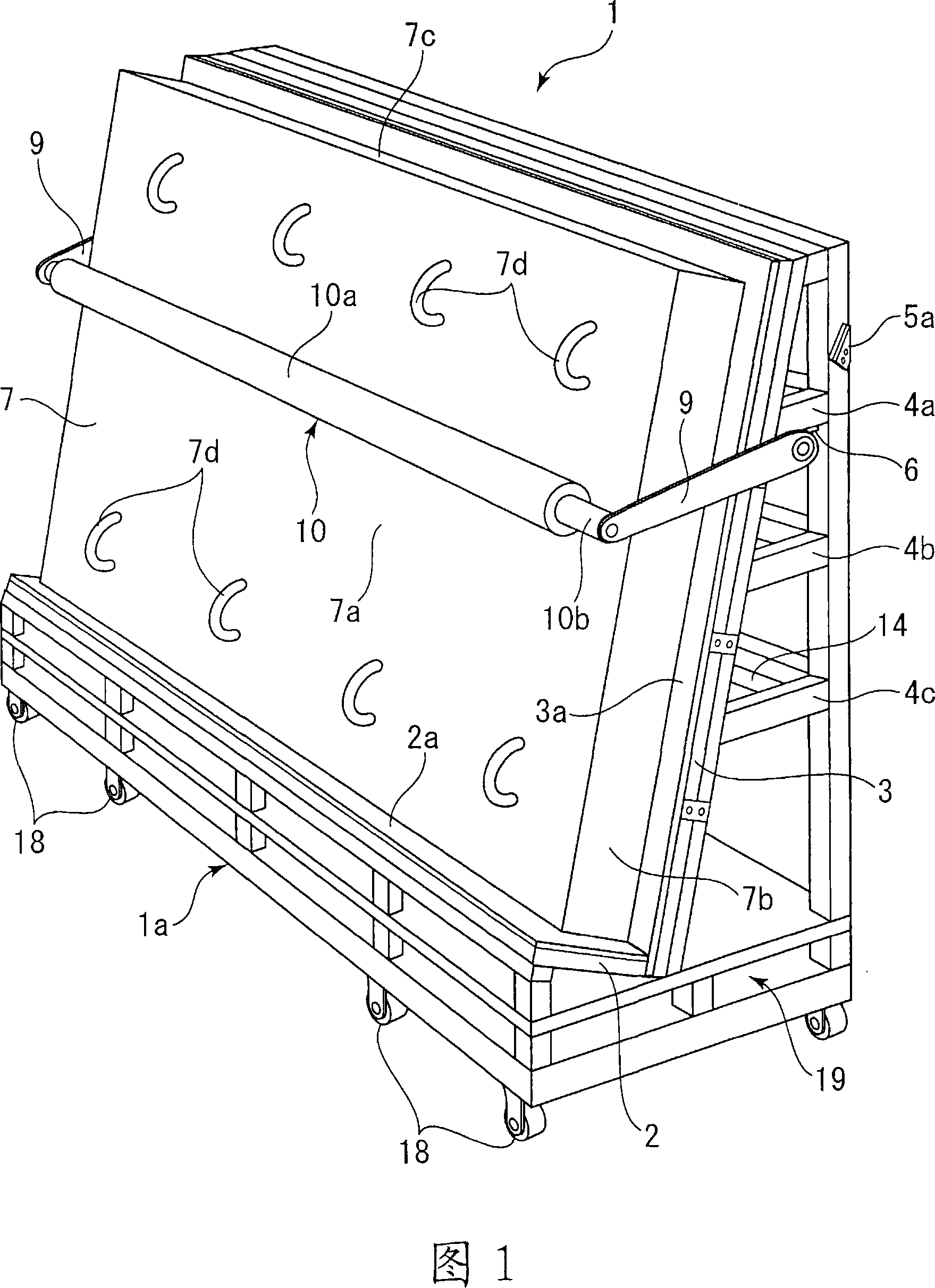
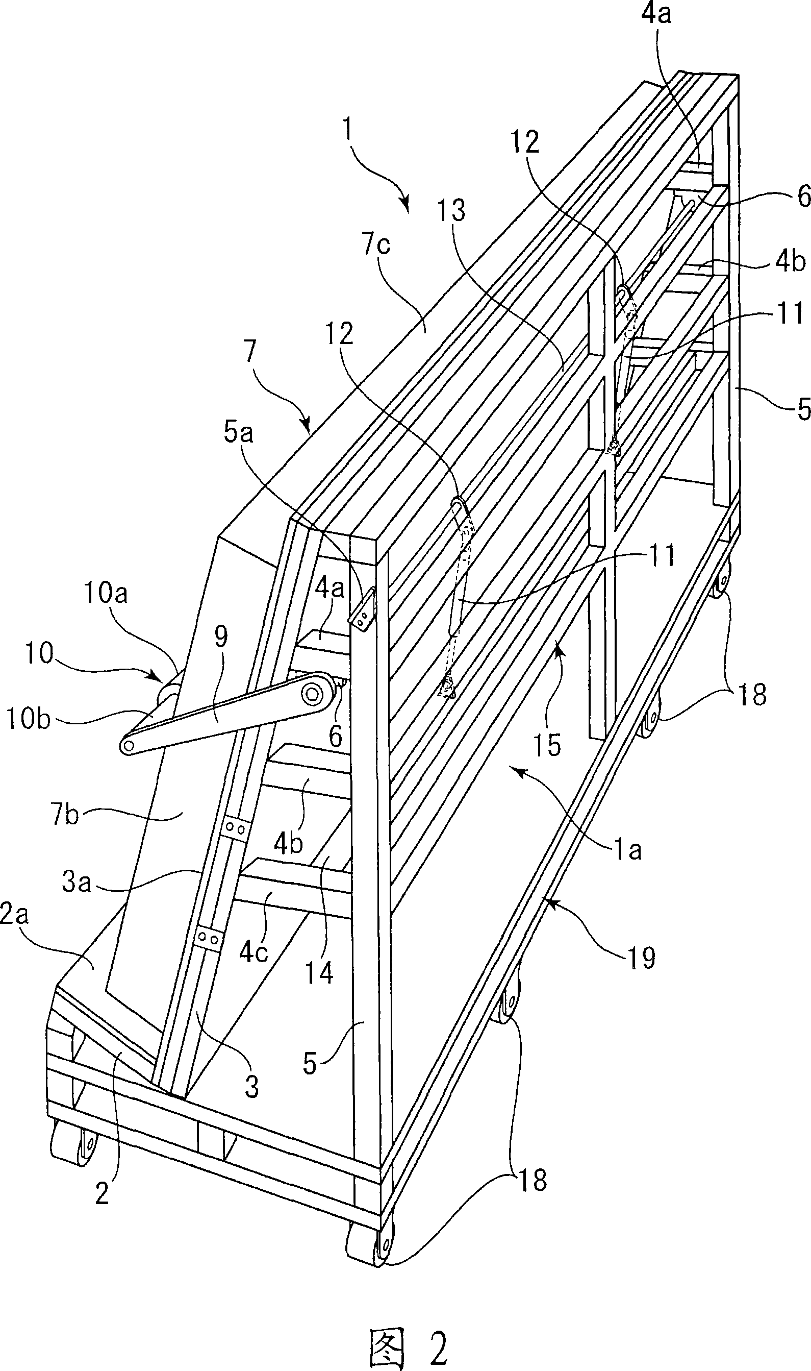
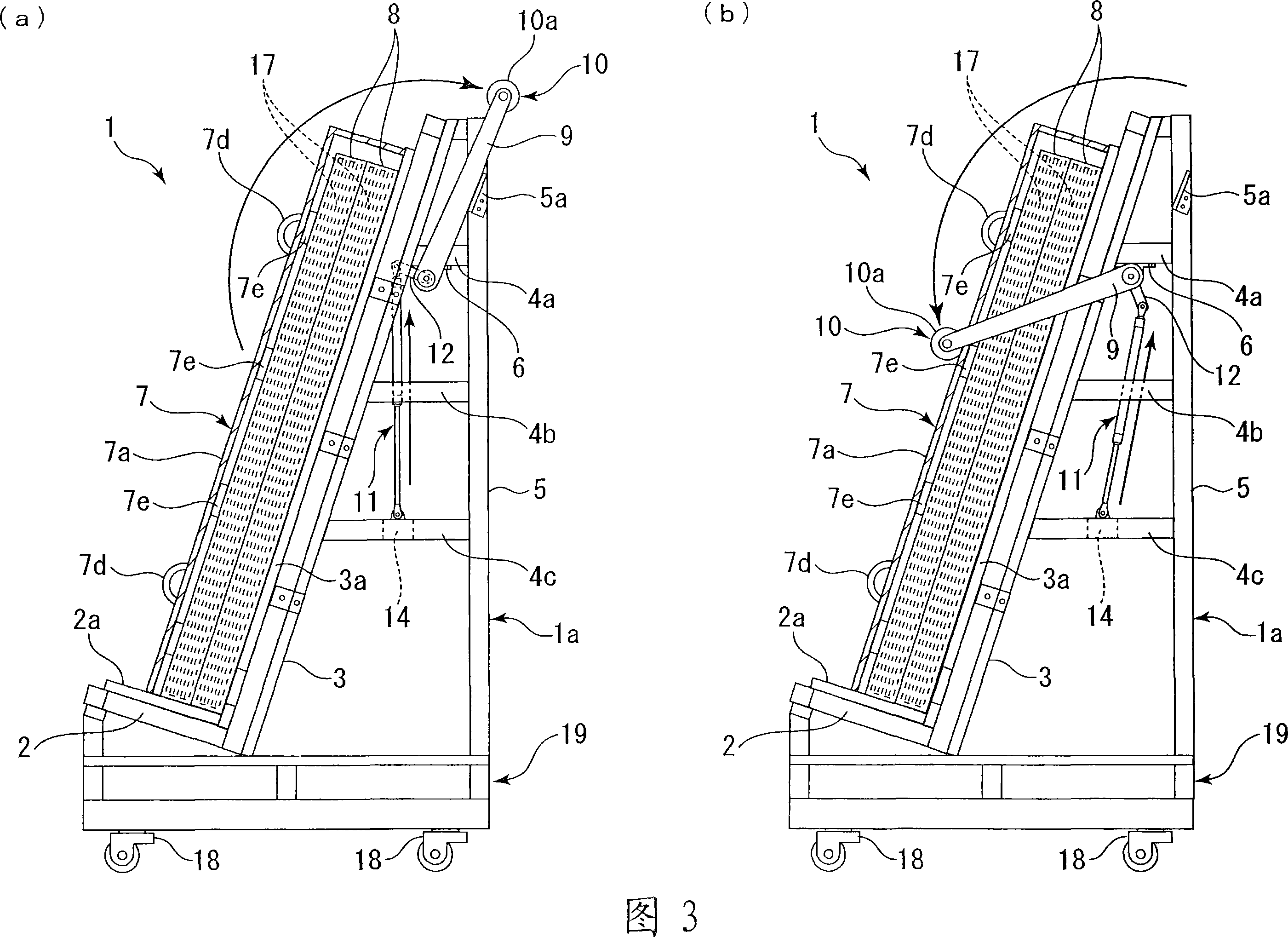
[0114]Fig. 1 is a perspective view showing the structure of the front side of the glass plate conveying tray in Embodiment 1 of the present invention, Fig. 2 is a perspective view showing the structure of the back side of the glass plate conveying tray, and Fig. 3 is a perspective view showing the structure of the glass plate conveying tray Partial cut-away side view of the side surface structure, (a) is a side view showing the state after the packing box is released from the central rod, the packing box accommodates a plurality of glass plates covered with a glass cover, (b) shows A side view of a state where the central rod is moved downward and the sealing box is held by the central rod through the glass cover.
[0115] This glass plate conveyance pallet (hereinafter referred to as a conveyance pallet) can vertically stack and convey a plurality of glass plates, and is used as a trolley for conveying and moving glass plates. Therefore, when Embodiment 1 of the present inven...
Embodiment 2
[0130] Fig. 4 is a perspective view showing the front side structure of the glass plate conveying carriage in Embodiment 2 of the present invention, Fig. 5 is a partially broken side view showing the side structure of the glass plate conveying carriage, Fig. 5 (a) is a diagram showing A side view of a state in which the packaging box is released from the central rod. The packaging box accommodates a plurality of glass plates covered by a glass cover provided with reinforcing rods. FIG. 5(b) shows that the central rod is moved downward and against Attached to the reinforcing rod, the side view of the state where the sealing box is held with the central rod by means of the glass cover. In addition, in the following embodiment 2, the parts having the same configuration as those of the above-mentioned embodiment 1 are given the same symbols and their detailed descriptions are omitted.
[0131] The cover body 7 covering the packaging box 8 is formed of a hard plastic member, and is...
Embodiment 3
[0137] The way in which the glass plate 17 is placed on the bracket body 1a is not limited to Examples 1 and 2, and Example 3 will be described with reference to FIG. 6 . In addition, in the following embodiment 3, the parts having the same configuration as those of the above-mentioned embodiment 1 are given the same symbols to omit their detailed description.
[0138]First, Fig. 6 (a) shows a side view of a modified example of directly holding the glass plate 17 with the central rod 10, the bottom 17b of each glass plate is placed on the stage 2, and the rear surface portion 17c of the last glass plate Placed on the rear support 3 , a plurality of glass panes are laminated. Further, the central rod 10 directly contacts the vicinity of the central portion 17a of the frontmost glass plate 17' from above by swinging the support arm 9, and the laminated glass plate 17 is supported on the stage 2 side.
[0139] Furthermore, even when the laminated glass plates 17 are directly sup...
PUM
 Abstract
Description
Claims
Application Information
 - R&D
- Intellectual Property
- Life Sciences
- Materials
- Tech Scout
- Unparalleled Data Quality
- Higher Quality Content
- 60% Fewer Hallucinations
Browse by: Latest US Patents, China's latest patents, Technical Efficacy Thesaurus, Application Domain, Technology Topic, Popular Technical Reports.
© 2025 PatSnap. All rights reserved.Legal|Privacy policy|Modern Slavery Act Transparency Statement|Sitemap|About US| Contact US: help@patsnap.com


