Supercharge Your Innovation With Domain-Expert AI Agents!

Flow barrel polishing device and polishing method

一种滚筒抛光、内筒的技术,应用在表面抛光的机床、磨削/抛光设备、磨床等方向,能够解决抛光能力和抛光效率下降等问题

Active Publication Date: 2008-04-16
SINTOKOGIO LTD
View PDF1 Cites 7 Cited by
  • Summary
  • Abstract
  • Description
  • Claims
  • Application Information

AI Technical Summary

Problems solved by technology

[0006] (2) The contact point pressure (that is, the polishing ability and polishing efficiency) of the part of the mass (M) close to the open domain will decrease

Method used


Image

  • Flow barrel polishing device and polishing method
  • Flow barrel polishing device and polishing method
  • Flow barrel polishing device and polishing method

Examples


Embodiment 1 and Embodiment 2

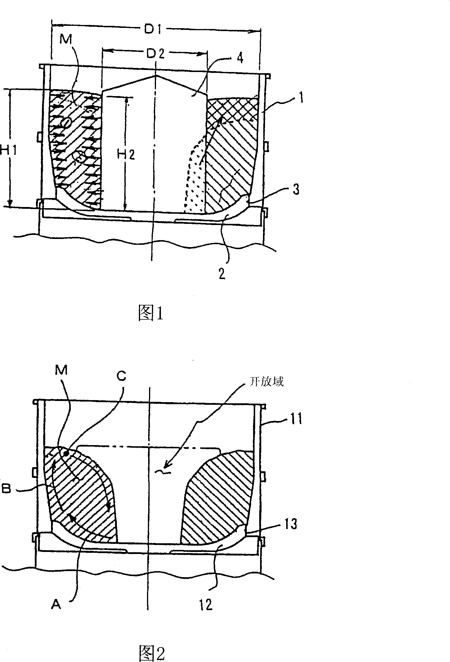
[0045]The flow tumbling apparatus shown in Table 1 was tested. In Example 1 and Example 2, an inner cylinder 4 is respectively arranged at the rotation center of the turntable 2, while Comparative Example 1 is not provided with an inner cylinder. The common test conditions are that the hard sample as the object to be polished (hereinafter, written as "workpiece") is made of material S45C, and the soft sample is made of material A2017, which is used as an abrasive material (hereinafter, written as "medium") There is a conical material with a base diameter of 20mm, a composite abrasive, and water, and the rotation speed of the turntable 2 is 250min -1 , The polishing time is 30min.

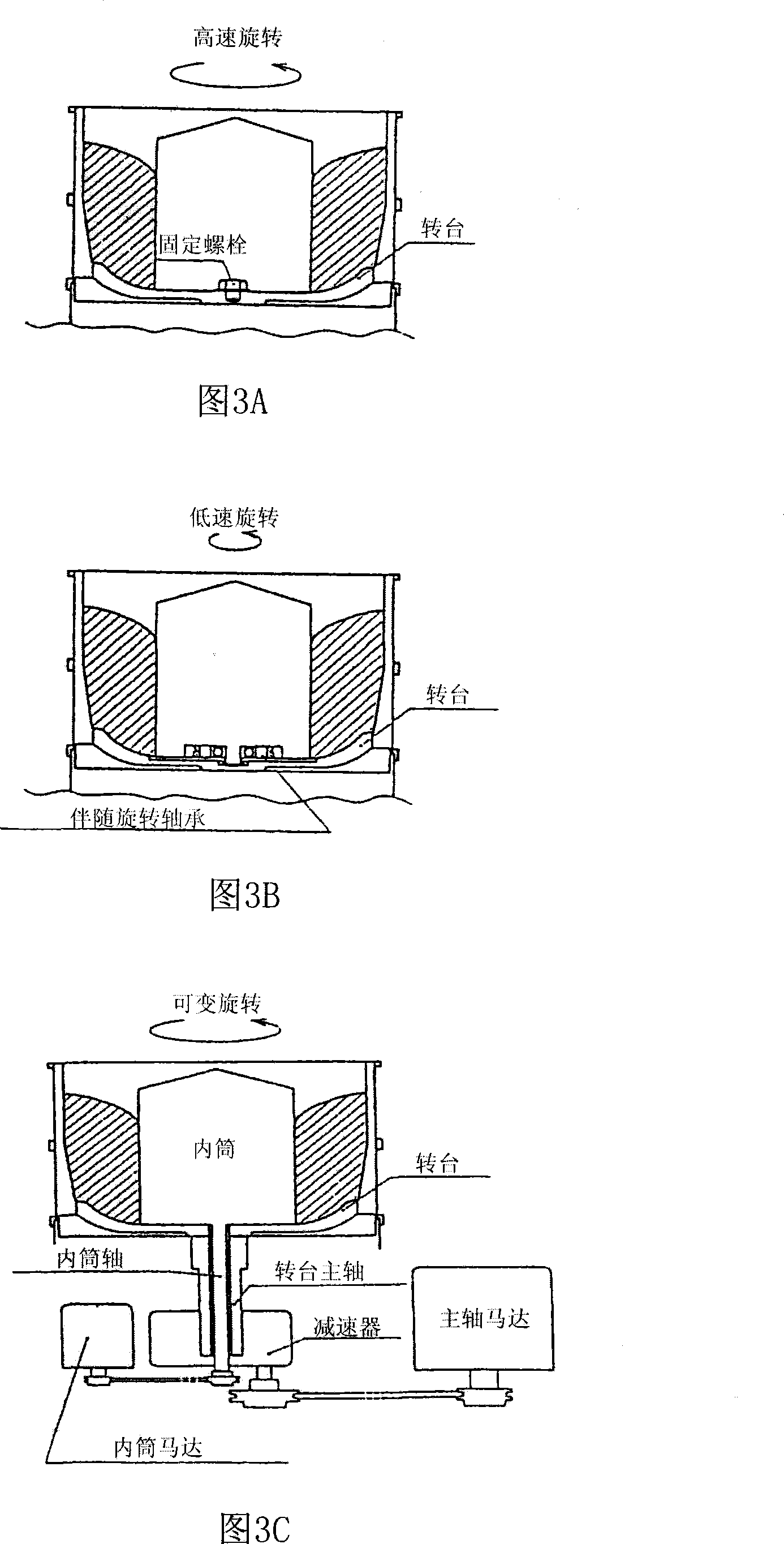
[0046] The diameter of the inner cylinder 4 in Embodiment 1 and Embodiment 2 is Φ220mm. In embodiment 1, inner cylinder 4 is tightly fixed on the rotation center of this turntable 2, as shown in Figure 1, its rotational speed is identical with this turntable 2 (250min -1 ). In Embodiment 2, the ...

Embodiment 3、4 and 5

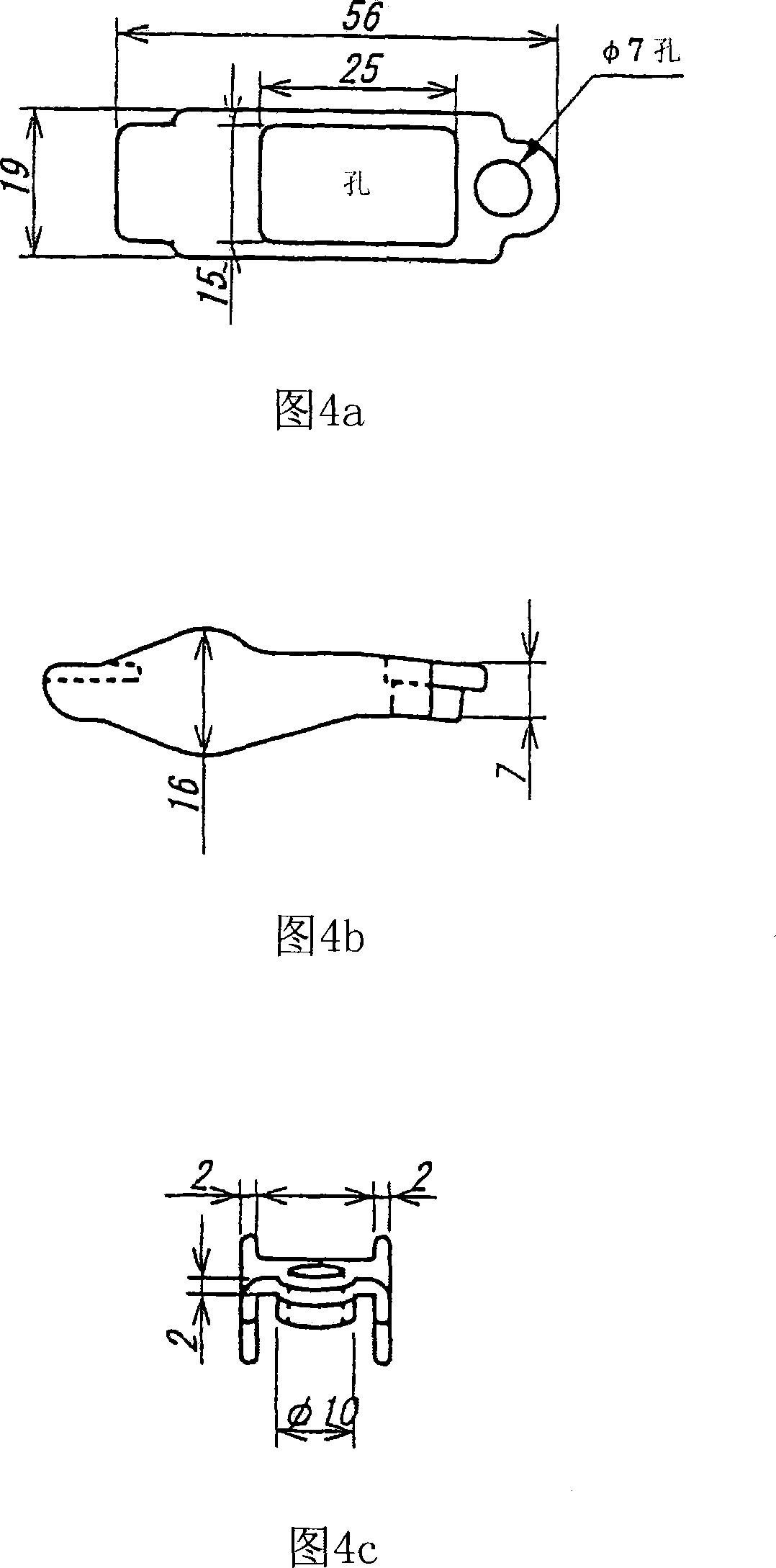
[0065] The flow tumbling apparatus listed in Table 3 were tested. Embodiments 3, 4 and 5 each have an inner cylinder 4 disposed at the rotation center of a turntable 2 . However, Comparative Example 2 did not have an inner cylinder. The common test conditions were an actual workpiece, a rocker arm made of SCM used as an automobile part, as an object (workpiece) to be polished. A test piece made of the same material as the actual workpiece is used as a reference. Than in embodiment 1 and embodiment 2 harder, smaller, have the fired ceramics of larger specific gravity, a composite abrasive and water, as medium. The rotation speed of turntable 2 is 250min -1 , The polishing time is 30min. This workpiece is used as a rocker arm of an automobile part, and its shape is shown in Figure 4.

[0066] In Examples 3 and 4, the outer diameter of the inner cylinder 4 is 220 mm, which is the same as in Examples 1 and 2. In Embodiment 5, the outer diameter of the inner cylinder is 260 m...


PUM


Abstract

A flow barrel polishing device has a hollow cylinder-like fixed container (1) and a rotary table (2) horizontally rotated with a sliding section gap (3) formed at the bottom of the fixed container (1). Work and media are placed in the fixed container (1) and the rotary table (2) is horizontally rotated. Then, the work and the media flow in a whirling manner to form a mass (M) and the work is polished. A fixed or rotatably supported hollow cylinder (4) is provided on the rotation center of the rotary table (2), and by this, the outer peripheral surface of the mass (M) is made to be in contact with the inner peripheral surface of the fixed container (1) and the inner peripheral surface of the mass (M) is made to be in contact with the outer peripheral surface of the hollow cylinder (4), thereby the work in the mass (M) is polished.

Description

technical field [0001] The invention relates to a flow drum polishing device and a polishing method, which can improve polishing ability and efficiency, improve productivity by shortening polishing time, and reduce operating cost by suppressing medium loss. Background technique [0002] Fig. 2 is a cross-sectional view of a conventional flow drum polishing device. As shown in FIG. 2 , a common flow drum polishing device includes a cylindrical fixed tank 11 , a turntable 12 located at the bottom of the tank 11 , and a gap 13 for the turntable to slide and rotate. [0003] The horizontal rotation of the turntable 12 generates a centrifugal force (A), which is transmitted from the center of rotation to the side wall of the fixed tank 11, and then to the workpiece and the medium in the tank 11. When the workpiece and the medium reach the side wall of the fixing groove 11, the centrifugal force (A) acting thereon is transformed into a lifting force (B). After the workpiece and ...

Claims


Application Information

Patent Timeline
Patent Type & Authority Applications(China)
IPC IPC(8): B24B31/108
CPCB24B31/108
Inventor 渡边昌知末菅启朗
Owner SINTOKOGIO LTD
Features
  • R&D
  • Intellectual Property
  • Life Sciences
  • Materials
  • Tech Scout
  • Unparalleled Data Quality
  • Higher Quality Content
  • 60% Fewer Hallucinations
Learn More