

Elevator apparatus
A technology for elevators and control devices, applied in the directions of transportation, packaging, elevators, etc., can solve the problems of the car rushing into the end of the hoistway without consideration, etc.
- Summary
- Abstract
- Description
- Claims
- Application Information
AI Technical Summary
Problems solved by technology
Method used
Image

Examples
no. 1 Embodiment approach
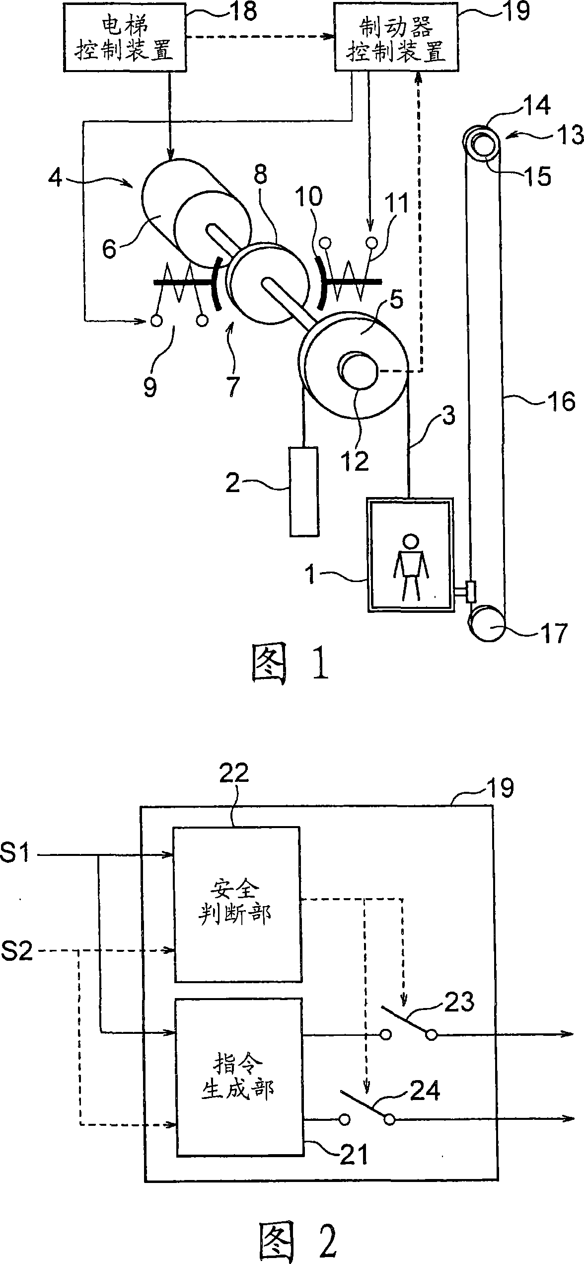
[0017] Fig. 1 is a configuration diagram showing an elevator apparatus according to a first embodiment of the present invention. In the figure, the car 1 and the counterweight 2 are suspended in the hoistway by the main rope (suspension unit) 3, and are raised and lowered in the hoistway by the driving force of the winch 4. The hoist 4 has a drive sheave 5 around which a main rope 3 is wound, a motor 6 that rotates the drive sheave 5 , and a brake unit 7 that brakes the rotation of the drive sheave 5 .
[0018] The brake unit 7 has a brake gear 8 that rotates integrally with the drive pulley 5 and a brake device 9 that brakes the rotation of the brake gear 8 . A brake drum, a brake disc, or the like can be used as the brake gear 8 . The driving pulley 5, the motor 6 and the brake gear 8 are coaxially arranged.
[0019] The brake device 9 has a plurality of brake shoes 10 contacting / separating from the brake gear 8, a plurality of brake springs pressing the brake shoes 10 on ...
no. 2 Embodiment approach
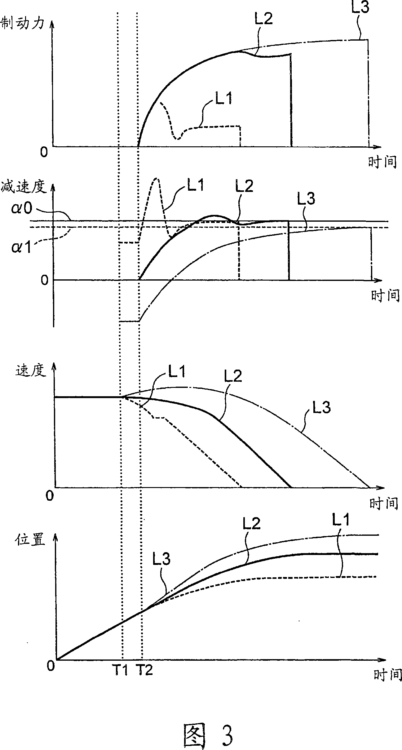
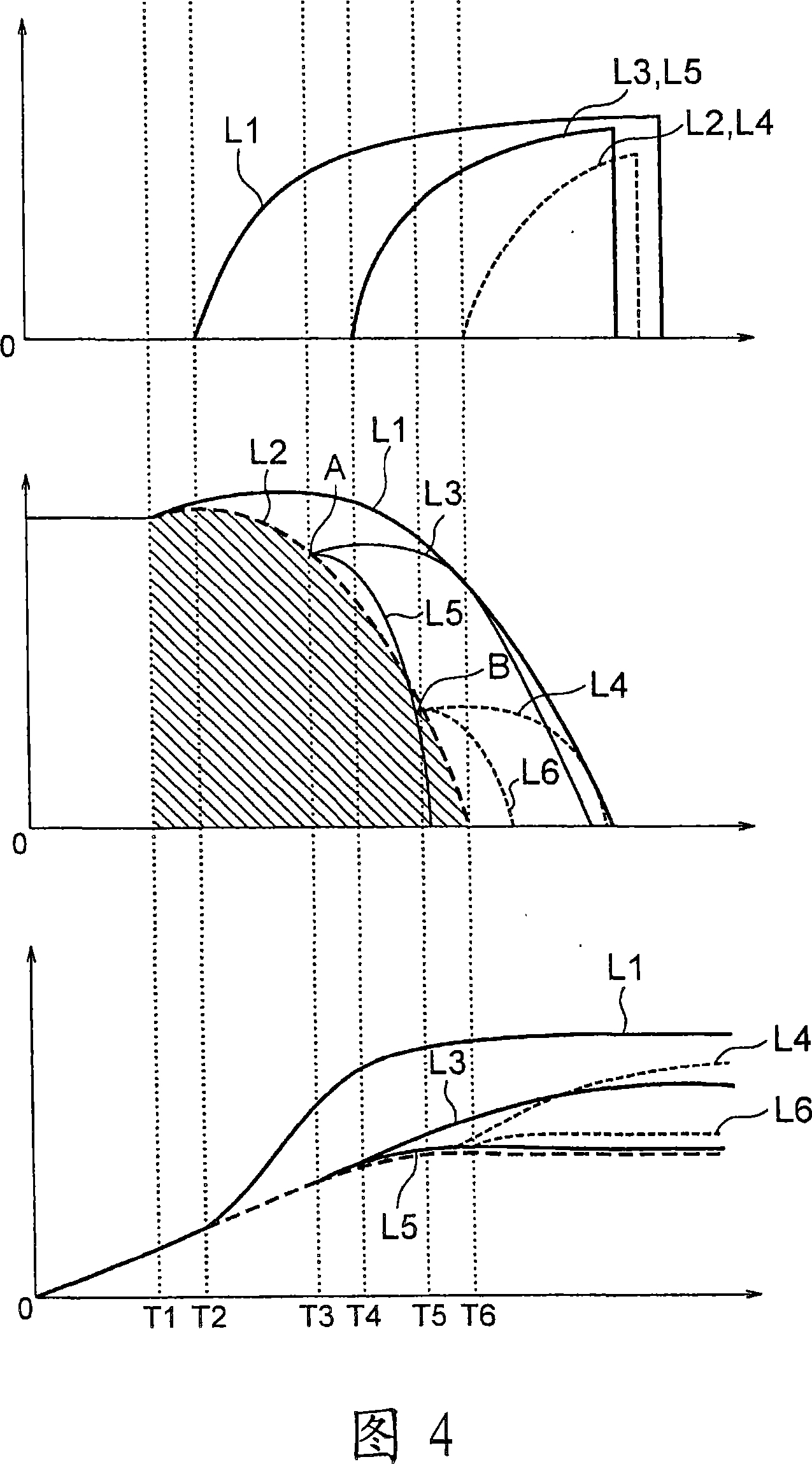
[0042] Next, FIG. 4 is a graph showing temporal changes in braking force, speed, and car position when deceleration control during emergency braking is performed by the brake control device 19 of the elevator apparatus according to the second embodiment of the present invention. In the second embodiment, the brake control device 19 monitors the speed of the car and the time since the emergency stop command was issued as the running state of the car 1 . Moreover, only when the brake device 9 is in an emergency braking state and the car speed in FIG. 4 is within the allowable area of the oblique line, the brake control device 19 closes the safety relays 23 and 24, so that the braking force reduction control is effective. Other structures and operations are the same as those of the first embodiment.
[0043] A solid line L1 in the figure represents a change in the state quantity when the stopping distance is the longest. Therefore, if the car 1 stops at a distance shorter than...
no. 3 Embodiment approach
[0050] Next, a third embodiment of the present invention will be described.
[0051] The second embodiment is based on the premise that the loaded state of the car 1 is unknown, so even if the relationship between the loaded state of the car 1 and the direction of travel is the condition that the stopping distance is the longest, the safety relays 23 and 24 are also controlled to make the car 1 Car 1 stops within the allowed stopping distance. Therefore, if the car 1 is in a state where it is easy to decelerate, for example, the speed curves from point A and point B in FIG. Therefore, as long as it is grasped that the car 1 is in a state where it is easy to decelerate, the allowable area can be expanded toward the side of the solid line L1.
[0052] 5 is a graph showing temporal changes in braking force, speed, and car position when deceleration control during emergency braking is performed by the brake control device 19 of the elevator apparatus according to the third embodi...
PUM
 Abstract
Description
Claims
Application Information