ECG-gated temporal sampling in cardiac kinetic modeling

A technology of time and duration, applied in the fields of radiological diagnosis instruments, medical science, acoustic wave diagnosis, etc., can solve the problems such as the inability to accurately display the dynamic changes of image time, and achieve the effect of improving image resolution.

Inactive Publication Date: 2010-06-16
KONINKLIJKE PHILIPS ELECTRONICS NV
View PDF5 Cites 0 Cited by
  • Summary
  • Abstract
  • Description
  • Claims
  • Application Information

AI Technical Summary

Problems solved by technology

However, time-averaged images cannot accurately represent the dynamic changes of the image with respect to time

Method used


Image

  • ECG-gated temporal sampling in cardiac kinetic modeling
  • ECG-gated temporal sampling in cardiac kinetic modeling
  • ECG-gated temporal sampling in cardiac kinetic modeling

Examples


Embodiment Construction

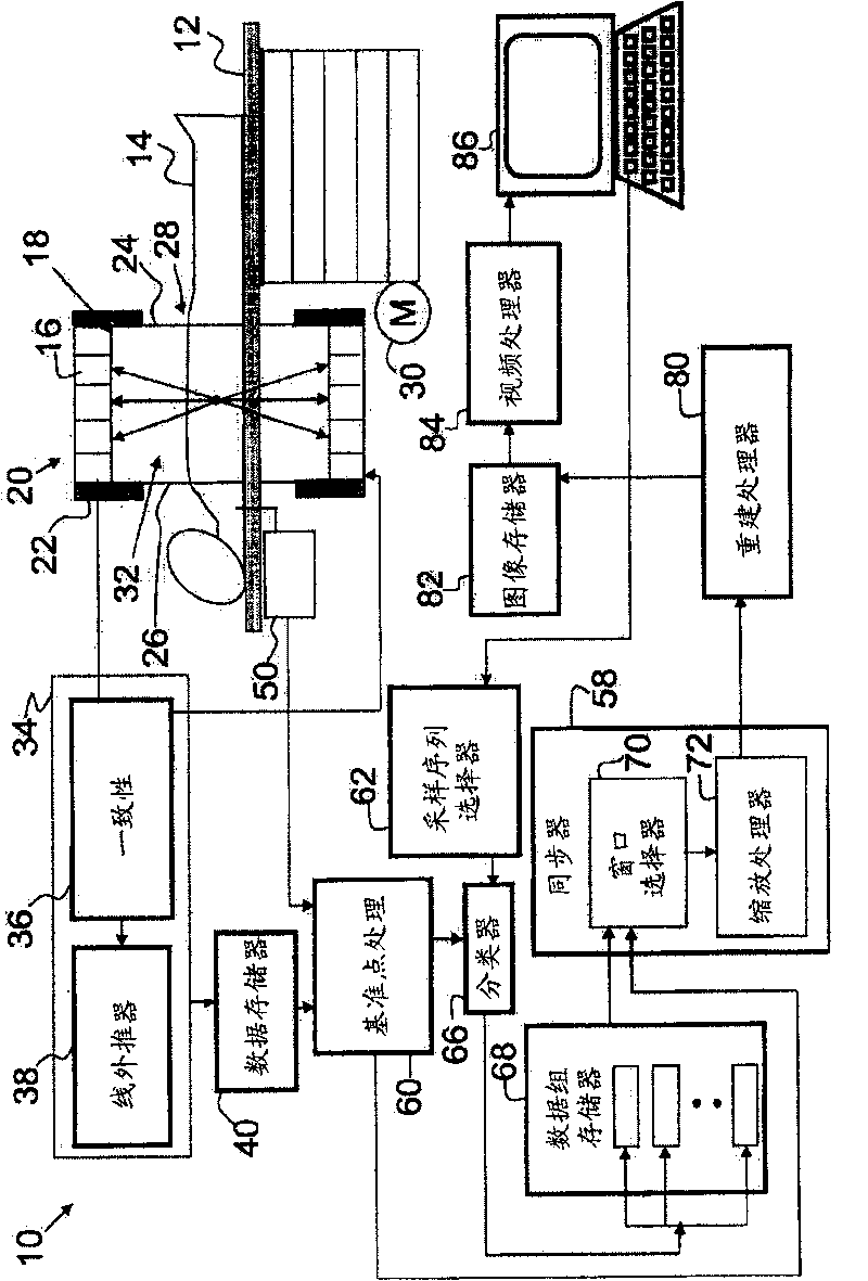
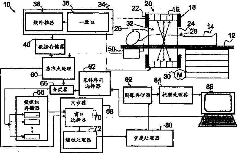
[0017] refer to figure 1 , the imaging system 10 includes a subject support device 12, such as a table or sofa, which supports a subject 14 to be imaged. Subject 14 is injected with one or more radioactive isotopes or tracers to induce positron emission. A cylindrical, annular array of detectors 16 is arranged around an aperture 18 of a PET scanner gantry 20 forming an axial field of view. When the detectors have flat surfaces, the detector array 16 may be octagonal or other polygonal shape that approximates a circle. The detector units are preferably mounted in sub-arrays mounted end-to-end to form the detector array 16 . A radiation end shield 22 is mounted at the entrance 24 and exit 26 of the circular aperture 18 to form a reception area or entrance window 28 of the PET scanner 20 .

[0018] An actuator 30, such as a motor, extends and / or retracts the object support 12 to achieve a desired positioning of the object 14 within the examination region 32 defined by the aper...


PUM


Abstract

In a diagnostic imaging system (10), a monitor (50) monitors periodic biological cycles of the subject (14). A trigger point detector (60) detects a time (tl, t2, ..., tn) of a common, reoccurring reference point (Rl, R2, ..., Rn) in each periodic cycle of the subject (14). A sequence selector (62) selects a sequence (64) of nominal sampling segments (Si, S2, ..., Sn). An adjustor (70) adjusts duration of each nominal sampling segment (Si, S2, ..., Sn) to coincide with the times of detected reference points (Rl, R2, ..., Rn). A scaling processor (72) scales each adjusted segment based on a difference in duration between the corresponding nominal (Si, S2, ..., Sn) and adjusted sampling segments (S'i, S'2, ..., S'n).

Description

technical field [0001] The present invention relates to the field of diagnostic imaging. The present invention relates to and will be described with particular reference to particular applications in connection with positron emission tomography (PET) dynamic imaging. However, it should be understood that the present invention is applicable to SPECT, magnetic resonance imaging systems, computed tomography imaging systems, ultrasound, etc. for a variety of imaging applications. Background technique [0002] Dynamic imaging refers to tracer measurements made over time. PET provides the tissue tracer concentration measurements required for tracer dynamic models, the end result of which is an image of the anatomical distribution of the biological process under study. The "tracer kinetic assay" method uses a radiolabeled, biologically active compound (tracer) and a mathematical model describing the dynamics of the radiolabeled tracer to describe the distribution of the tracer in...

Claims


Application Information

Patent Timeline
Patent Type & Authority Patents(China)
IPC IPC(8): A61B5/04
CPCA61B8/5276A61B6/541A61B6/037A61B8/543A61B5/02755A61B5/7289A61B6/5288
Inventor D·加格农H·布拉斯
Owner KONINKLIJKE PHILIPS ELECTRONICS NV
Why Eureka
Try Eureka