Compressed air brake cylinder

A technology of compressing air and brake cylinders, applied in the direction of brakes, brake components, brake types, etc., can solve problems such as difficulties

Inactive Publication Date: 2008-05-07
WABCO GMBH
View PDF1 Cites 5 Cited by
  • Summary
  • Abstract
  • Description
  • Claims
  • Application Information

AI Technical Summary

Problems solved by technology

Also, maintaining a certain length tolerance is difficult

Method used


Image

  • Compressed air brake cylinder
  • Compressed air brake cylinder
  • Compressed air brake cylinder

Examples


Embodiment Construction

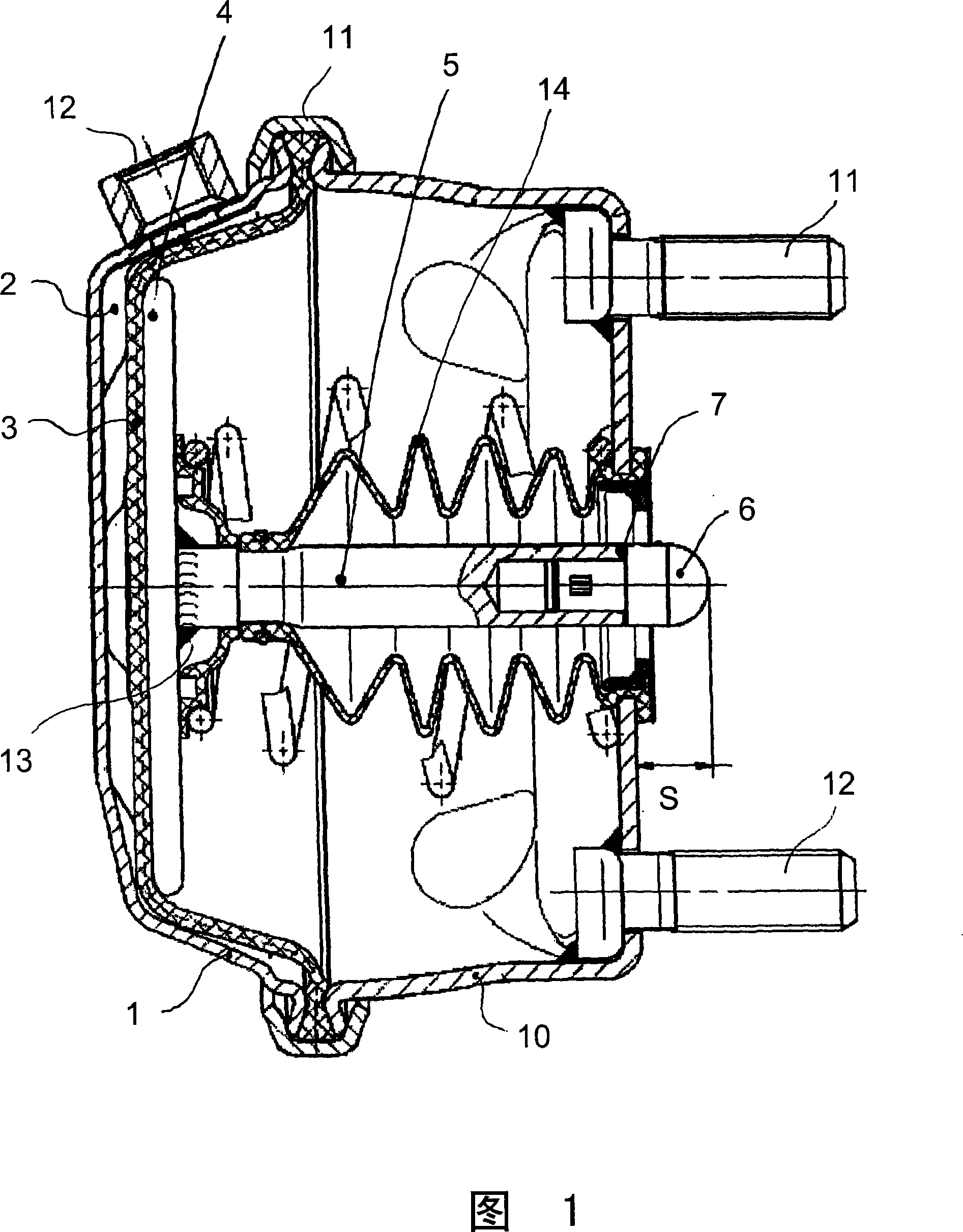
[0013] In FIG. 1, a compressed air brake cylinder of the prior art, in particular operating a disc brake of an automobile, is shown. It is formed by two shell covers 1, 10, which are joined together by curling edges 11. The housings 1 and 10 are fixed at suitable positions in the motor vehicle by means of fixing screws 11 and 12. The brake cylinder shown also includes a piston formed by a piston disk 4 and a piston rod 5. An independent pressure part 6 is installed on the right end of the piston rod 5, and the pressure part can be adjusted longitudinally by means of a compensation washer 7. Therefore, the length tolerance of the piston rod 5 can be compensated.

[0014] The brake cylinder also includes a rubber membrane 3 on which the piston disk 4 is supported.

[0015] Figure 1 shows the pistons 4, 5 in an entering state. The compressed air is supplied to the ventilation chamber 2 through the compressed air connection 12 to operate the piston. As a result, the pistons 4, 5 move ...


PUM


Abstract

Disclosed is a compressed air brake cylinder for controlling vehicle disk type brake, which is provided with a piston composed of a piston disk and a piston rod, and is made as a single-piece by cold forming of a raw material, so as to save materials and reduce tolerance.

Description

Technical field [0001] The invention relates to a compressed air brake cylinder according to the preamble of claim 1. Background technique [0002] For example, DE10244916B4 discloses such a brake cylinder. It relates to a spring accumulator brake cylinder with a spring operated rear piston and a compressed air operated front piston. The front piston is formed by a pressure plate and a joystick fixed in it. The pressure plate is supported on the rubber membrane. Vent a pressure chamber between the rubber membrane and the housing wall to manipulate the front piston. The connection between the joystick and the pressure plate is usually welded, for example by friction welding. [0003] However, in such a welding, the centering of the joystick is extremely important. In addition, it is difficult to maintain a certain length tolerance. Summary of the invention [0004] Therefore, the object of the present invention is to connect a piston of a compressed air brake cylinder formed by a...

Claims


Application Information

Patent Timeline
Patent Type & Authority Applications(China)
IPC IPC(8): F16D65/32F16D65/24F16J3/06F16D65/28F16D65/22
CPCB60T17/081
Inventor O·布兰特J·埃沃尔德A·里齐特F·斯查德
Owner WABCO GMBH
Why Eureka
Try Eureka