Variable valve control mechanism

A valve control and variable technology, applied in valve devices, mechanical equipment, engine components, etc., can solve the problems of the locking pin 14 not being able to enter the accommodating space smoothly, the influence of valve actuation, and the failure of lift switching.

Inactive Publication Date: 2011-07-20
IND TECH RES INST
View PDF1 Cites 0 Cited by
  • Summary
  • Abstract
  • Description
  • Claims
  • Application Information

AI Technical Summary

Problems solved by technology

In this design, when the outer jacking cylinder 10 and the inner jacking cylinder 11 are to be connected, but if the locking pin 14 is not on the same straight line as the hole, the locking pin 14 will not be able to enter the accommodation space 102 smoothly, and the head switching will fail.
[0005] In addition, when this type of design is in a low-lift state, the low-lift cam will press down on the inner jack 11 to drive the valve. At this time, the high-lift cam will still press down on the outer jack 10, although the displacement of the outer jack 10 can be controlled by the inside of the jack. However, if the design of the spring 16 in the ejector group is poor, or the high-lift cam still presses down on the outer ejector when the valve is closed, it will exert a force on the valve spring 16, which will affect the valve spring 16 in the low-lift state. Valve actuation affects

Method used


Image

  • Variable valve control mechanism
  • Variable valve control mechanism
  • Variable valve control mechanism

Examples


Embodiment Construction

[0035] In order to have a further cognition and understanding of the features, purpose and functions of the present invention, the relevant detailed structure and design concept of the device of the present invention will be described below, and the detailed description is as follows:

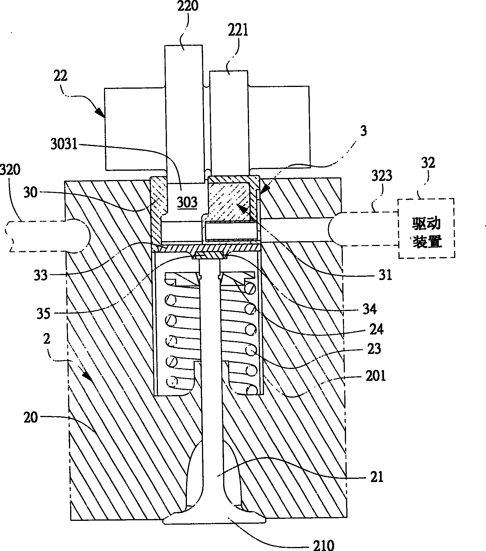
[0036] see figure 2 As shown, the figure is a schematic diagram of the combined state of the first preferred embodiment of the variable valve control mechanism of the present invention and the engine. The variable valve control mechanism 3 can control the lift of the valve through the driving force provided by an actuating mechanism 22. The variable valve control mechanism 3 includes an outer push cylinder 30, a slide block 31 and A driving device 32 . The outer jack 30 is disposed in the cylinder head 20 of the engine 2 and abuts against a valve rod 21 . A receiving space 303 is defined in the outer jack 30 , and the receiving space has an opening 3031 . The slider 31 is disposed in the acc...


PUM


Abstract

The present invention relates to a variable valve control mechanism, characterized in that the movement of a sliding block is controlled so as to make the variable valve control mechanism driven by an actuating mechanism, further control the opening of an engine valve for producing high lift or low lift and achieve the switching effect between high lift and low lift. The design provided by the present invention can solve the switching failure of the traditional hole-pin connecting mechanism due to the inaccurate positioning in the lift switching. In the better practical examples of the present invention, the actuating mechanism in high lift does not contact the variable valve control mechanism when the valve is in low lift, so the valve motion will not be affected even in low lift. Thereby, the present invention can make the engine operate with better combustion efficiency under an appropriate rotating speed and reduce the oil consumption.

Description

technical field [0001] The invention relates to a valve control mechanism, in particular to a variable valve control mechanism which utilizes the movement of a control slider to selectively receive the driving force of an actuating mechanism and then controls the lift opening state of the valve. Background technique [0002] In recent years, the price of oil has skyrocketed, and the fuel consumption performance of engines has been paid more attention. According to the research data, the importance of the variable valve control mechanism technology is quite high, because the technology is the basis of many technologies such as cylinder deactivation and engine downsizing. [0003] Among them, in the variable valve mechanism, most of the mechanisms are as designed in US Patent No. US. Pat. No. 6,223,706 B1. see figure 1 As shown, the variable valve mechanism 1 has a hollow outer top cylinder 10, an inner top cylinder 11 is located inside the outer top cylinder 10 and can slid...

Claims


Application Information

Patent Timeline
Patent Type & Authority Patents(China)
IPC IPC(8): F01L13/00
Inventor 吴敏全刘达全
Owner IND TECH RES INST
Why Eureka
Try Eureka