Conveyor and freight trolley

A conveyor and transmission mechanism technology, applied in the field of automation, can solve problems such as inability to transmit goods, stuck goods, and failed delivery of goods

Pending Publication Date: 2019-12-24
BEIJING SANKUAI ONLINE TECH CO LTD
View PDF0 Cites 3 Cited by
  • Summary
  • Abstract
  • Description
  • Claims
  • Application Information

AI Technical Summary

Problems solved by technology

However, for some cylindrical goods, it is easy to get stuck on the conveyor of delivery trolley A, so that the goods cannot be transferred to the conveyor of delivery trolley B, resulting in the failure of the delivery of goods

Method used


Image

  • Conveyor and freight trolley
  • Conveyor and freight trolley
  • Conveyor and freight trolley

Examples


Embodiment Construction

[0041] In order to make the purpose, technical solution and advantages of the present application clearer, the implementation manners of the present application will be further described in detail below in conjunction with the accompanying drawings.

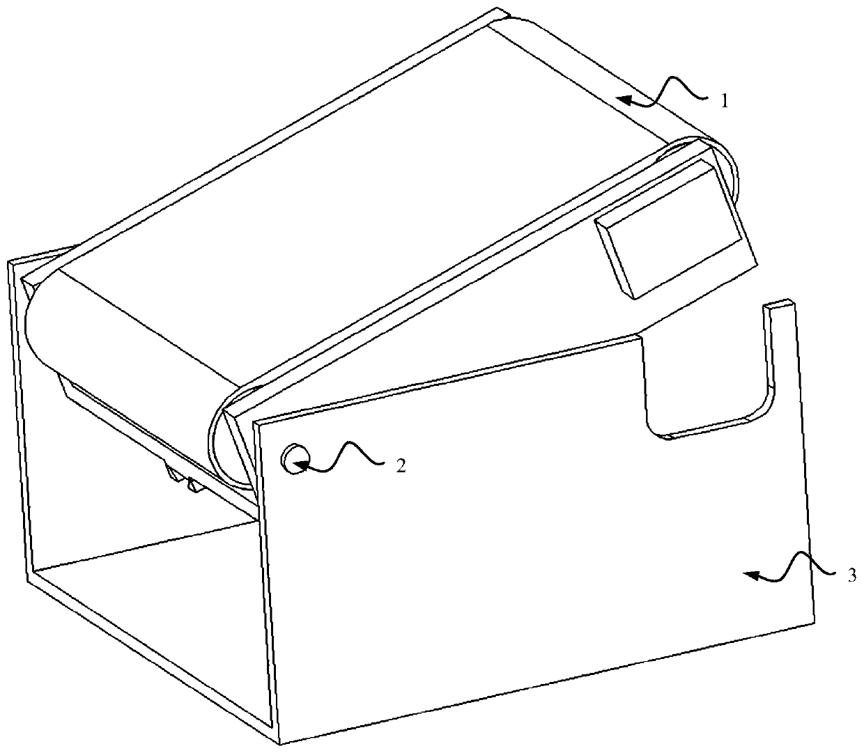
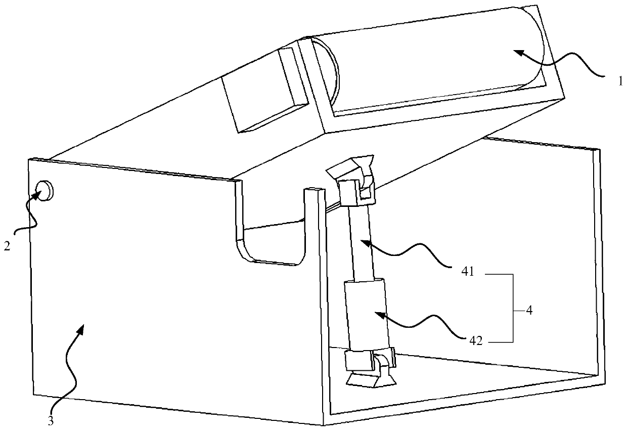
[0042] figure 1 It is a structural schematic diagram of the front view angle of a conveyor provided in the embodiment of this application, figure 2 It is a structural schematic diagram of the rear view angle of a conveyor provided in the embodiment of this application. see figure 1 and figure 2 , the conveyor may include: a transmission mechanism 1, a first rotating shaft 2, a bracket 3, a lifting mechanism 4 and a controller. The first rotating shaft 2 is rotatably connected to the first end of the transmission mechanism 1, and the first rotating shaft 2 is fixed on the bracket 3, the first end of the lifting mechanism 4 is movably connected to the transmitting mechanism 1, and the second end of the lifting mechanism 4 Con...


PUM


Abstract

An embodiment of the invention discloses a conveyor and a freight trolley, and belongs to the field of automation. The conveyor comprises a transferring mechanism, a first rotating shaft, a support, alifting mechanism and a controller; the first rotating shaft is rotationally connected with the first end of the transferring mechanism and is fixed to the support; the first end of the lifting mechanism is movably connected with the transferring mechanism; the second end of the lifting mechanism is connected with the support; and the lifting mechanism is electrically connected with the controller and is used for adjusting the height of the second end of the transferring mechanism under the control of the controller. According to the conveyor, the height of the second end of the transferringmechanism can be adjusted, so that the transferring mechanism forms an inclined slope. Thus, some goods clamped on the transferring mechanism can reach the first end of the transferring mechanism along the slope of the transferring mechanism under the action of gravity and then are transferred onto the next conveyor butt-jointed with the conveyor through rotation of the transferring mechanism, andthe condition of failure of handover of the goods is avoided.

Description

technical field [0001] The embodiment of the present application relates to the field of automation, and in particular to a conveyor and a delivery trolley. Background technique [0002] In unmanned factories and unmanned warehousing, it is more and more common to transport goods by delivery trucks. In the related art, the delivery trolley usually includes a truck body and a conveyor located on the top of the truck body. In a possible scenario, when the delivery trolley A needs to transfer the loaded goods to the delivery trolley B, first, it needs Connect the conveyor of the delivery trolley A to the conveyor of the delivery trolley B, and then transfer the goods on the delivery trolley A to the delivery trolley B through the rotation of the two conveyors to complete the handover of the goods. However, for some cylindrical goods, it is easy to get stuck on the conveyor of the delivery trolley A, so that the goods cannot be transferred to the conveyor of the delivery trolle...

Claims


Application Information

Patent Timeline
Patent Type & Authority Applications(China)
IPC IPC(8): B65G41/00B65G43/08B60P1/04B60P1/38
CPCB60P1/04B60P1/38B65G41/002B65G43/08
Inventor 傅强朱辰未杏龙
Owner BEIJING SANKUAI ONLINE TECH CO LTD
Why Eureka
Try Eureka