Sealing device

A sealing device and sealing component technology, applied in the direction of engine sealing, bearing components, engine components, etc., can solve the problems of insufficient sealing performance and insufficient length, and achieve the effect of improving sealing performance and inhibiting the intrusion of foreign objects such as mud and water.

Inactive Publication Date: 2008-05-28
NOK CORP
View PDF1 Cites 16 Cited by
  • Summary
  • Abstract
  • Description
  • Claims
  • Application Information

AI Technical Summary

Problems solved by technology

[0006] Conventionally, as shown in FIG. 6, since the outer peripheral cylindrical portion 52c is integrally formed on the outer peripheral portion of the oil slinger member 52, the entire length of the outer peripheral cylindrical portion 52c on the outer peripheral surface i

Method used


Image

  • Sealing device
  • Sealing device
  • Sealing device

Examples


no. 1 example

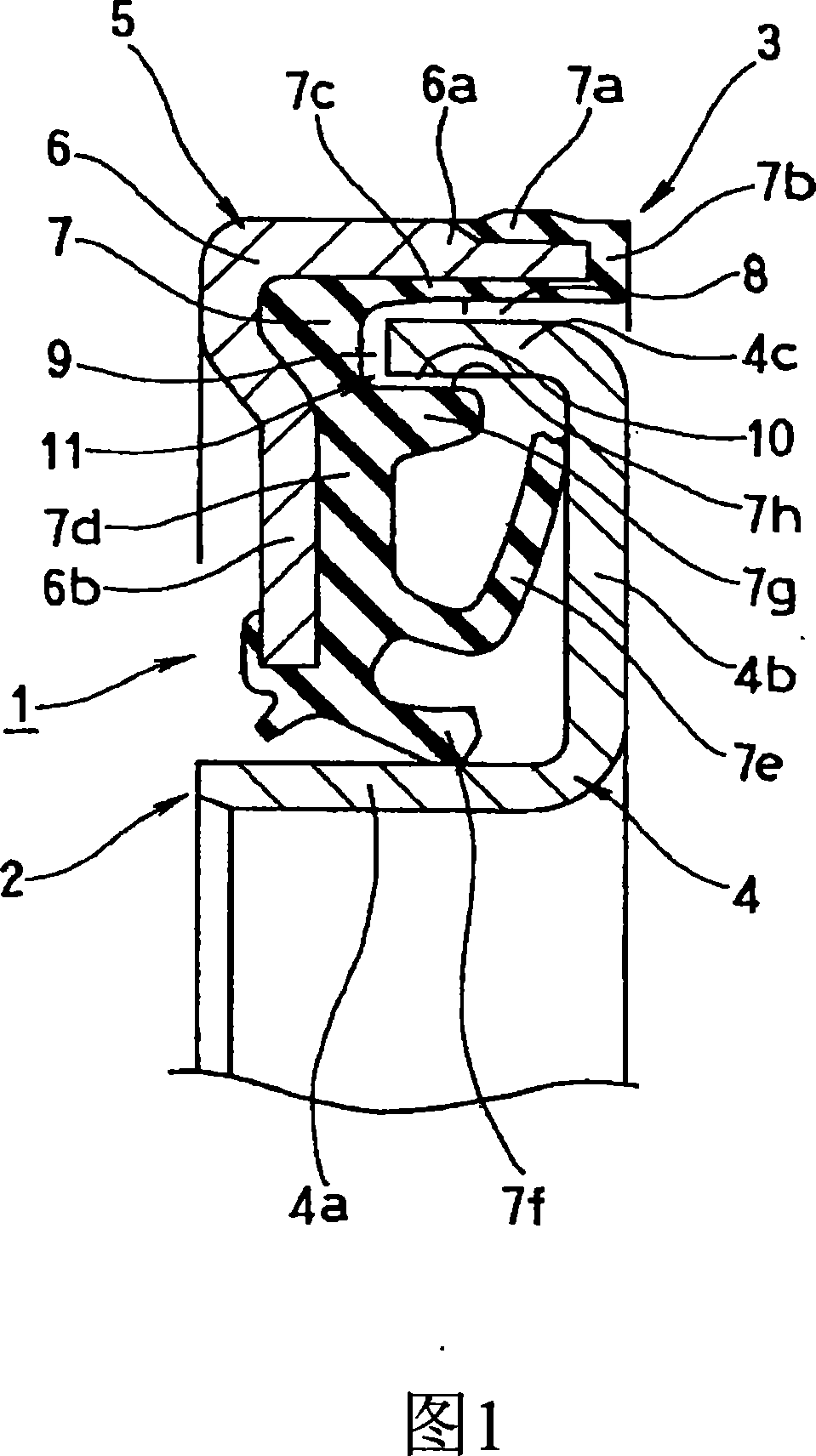
[0055] Fig. 1 shows a cross-sectional view of main parts of a sealing device 1 according to a first embodiment of the present invention. The sealing device 1 described in this embodiment is used for hub bearing seals (bearing pad seals) in the field of automobiles, and has the following structure. This embodiment is the embodiment described in relation to claim 1 of the present application.

[0056] That is, firstly, the sealing device 1 has an inner circumference mounted on a bearing inner ring (inner peripheral side mounting part, not shown in the figure) as one side member of the two relative rotation members, and rotates together with the bearing inner ring. A side seal member 2, and a non-rotating outer peripheral side seal member 3 mounted on the other side of the two parts, that is, the bearing outer ring (outer peripheral side mounting part, not shown in the figure).

[0057] The inner peripheral side seal member 2 is composed of an oil slinger member (hereinafter als...

no. 2 example

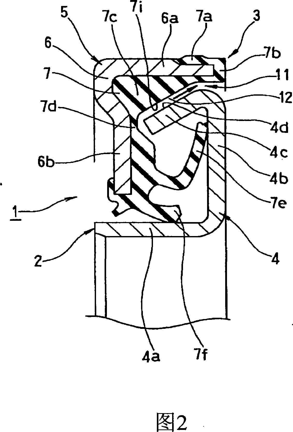
[0066] Fig. 2 shows a cross-sectional view of main parts of a sealing device 1 according to a second embodiment of the present invention. The sealing device 1 described in this embodiment is used for hub bearing seals (bearing pad seals) in the related automotive field, and its structure is as follows. This embodiment is related to the embodiment related to claim 2 of the present application.

[0067] That is, first, this sealing device 1 has an inner bearing inner ring (an inner peripheral side mounting member, not shown in the figure) which is one side member of two parts which rotate relatively, and which rotates together with the bearing inner ring. The peripheral side sealing member 2, and the non-rotating outer peripheral side sealing member 3 installed on the bearing outer ring (outer peripheral side mounting part, not shown in the figure) of the other part of the two parts.

[0068] The inner peripheral side seal member 2 is constituted by an oil slinger member (herei...

no. 3 example

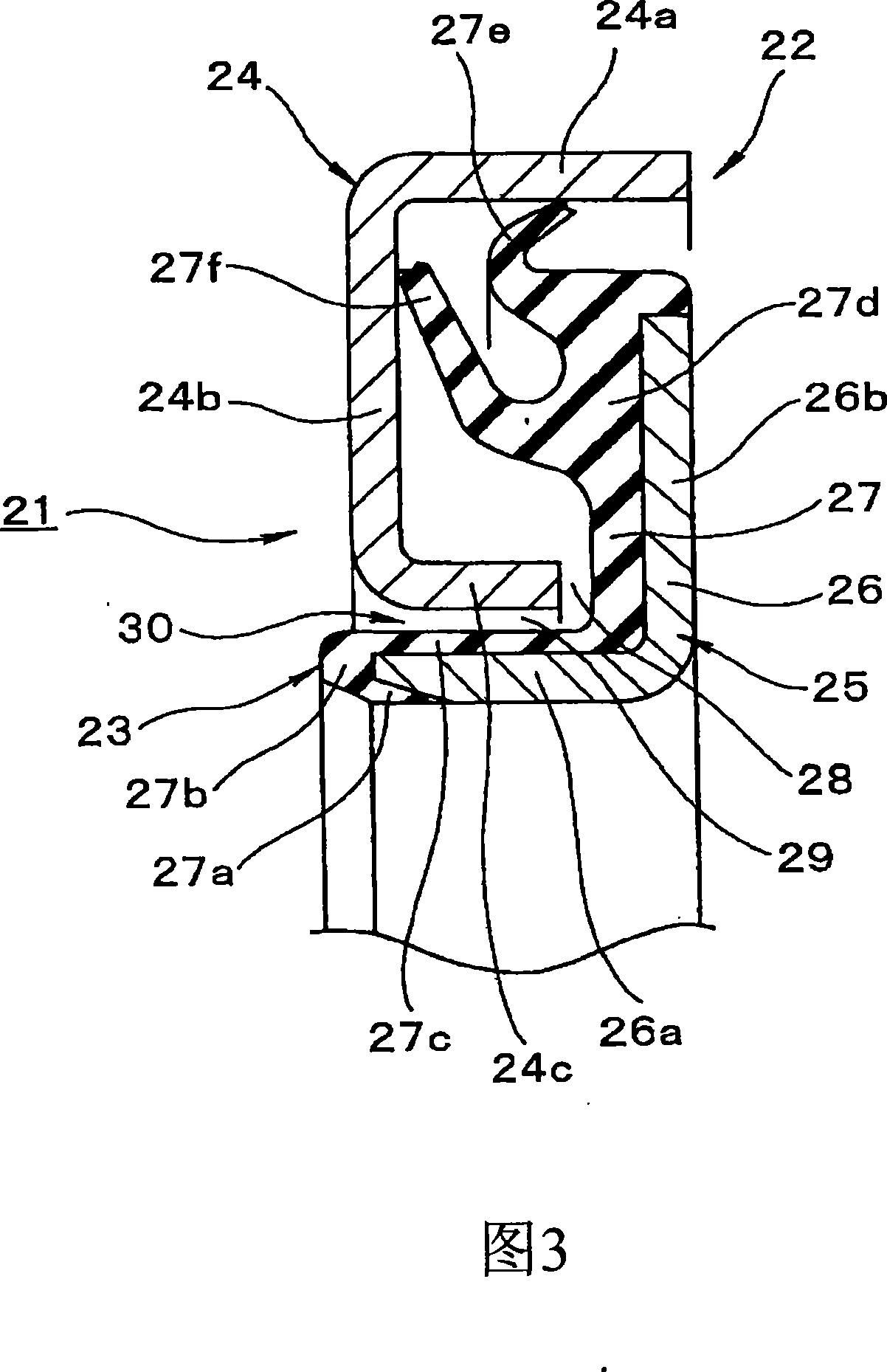
[0078] Fig. 3 shows a sectional view of a main part of a sealing device 21 according to a third embodiment of the present invention. The sealing device 21 described in this embodiment is used for hub bearing seals (pad seals) in the field of automobiles, and has the following structure. This embodiment is related to the embodiment related to claim 3 of the present application.

[0079] That is, firstly, the sealing device 21 has an outer peripheral side sealing member 22 which is mounted on the bearing outer ring (outer peripheral side mounting part, not shown in the figure) as one side part of the two parts which rotate relatively, and which does not rotate and a mounting part. An inner peripheral side sealing member 23 is on the other side of the two parts, that is, the bearing inner ring (the outer peripheral side mounting part, not shown in the figure) and rotates together with the bearing inner ring.

[0080] The outer peripheral side sealing member 22 is constituted by ...


PUM


Abstract

A sealing device (1) capable of further increasing sealing performance by a labyrinth to effectively suppress the entry of dust such as slurry, comprising an inner peripheral side sealing member (2) fitted to an inner peripheral side mounting member as one of two members rotating relative to each other and an outer peripheral side sealing member (3) fitted to the outer peripheral side mounting member as the other. An outer peripheral tube part (4c) is formed on the outer peripheral portion of the metal ring (4) of the inner peripheral side sealing member (2), and a series of long labyrinth spaces (8), (9), and (10) are formed between the outer peripheral surface of the outer peripheral tube part (4c) and the outer peripheral side sealing member (3), between the tip face of the outer peripheral tube part (4c) and the outer peripheral side sealing member (3), and between the inner peripheral surface of the outer peripheral tube part (4c) and the outer peripheral side sealing member (3).

Description

technical field [0001] The invention relates to a sealing device related to sealing technology. The sealing device of the present invention is used as a hub bearing seal in fields related to automobiles, or in general machinery and the like. Background technique [0002] In the past, there is known a sealing device 51 as shown in FIG. The oil slinger member 52 attached to the attachment member (for example, inner ring) 61 and the lip seal member 53 attached to the other outer peripheral side attachment member (for example, outer ring) 62 are combined. [0003] The oil slinger member 52 is made of metal material, and at one end of the cylindrical portion 52a in the axial direction, an annular radially raised portion 52b is integrally formed, and its cross section is approximately L-shaped, and the cylindrical portion 52a is embedded The inner peripheral side is mounted on the outer peripheral surface of a component (such as an inner ring) 61 . The structure of the lip seal...

Claims


Application Information

Patent Timeline
IPC IPC(8): F16J15/447F16C33/78F16C33/80F16J15/32F16J15/3232F16J15/3256
Inventor 神前刚松井宏树小林直人山中聪
Owner NOK CORP
Why Eureka
Try Eureka