

Connecting part and a steerable connecting part arrangement
A technology for connecting parts and assemblies, applied in the direction of connecting members, thin plate connections, pipes/pipe joints/pipe fittings, etc., can solve problems such as inability to apply inclination and inability to obtain locking
- Summary
- Abstract
- Description
- Claims
- Application Information
AI Technical Summary
Problems solved by technology
Method used
Image

Examples
Embodiment Construction
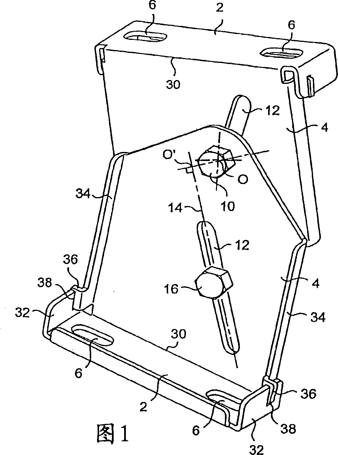
[0028] [28] In general, the connection according to the invention comprises a base 2 on the one hand and a plate 4 on the other hand. The base 2 and the plate 4 are perpendicular to each other.
[0029] [29] The base 2 is in the form of a narrow strip and includes elongated openings 6 for fixing the connectors on the support. In the embodiment shown in FIGS. 1 to 3 , the base 2 comprises two elongated orifices spaced apart from each other but with their longitudinal axes coincident. Any other configuration of openings for realizing the fastening of the base 2 to the support is conceivable here. There may be, for example, only circular holes, or one or more circular holes and one or more elongated holes, and the elongated holes may be oriented in different directions relative to the elongated holes in FIG. 1 .
[0030] [30] The plate 4 may be of any shape. It has one side corresponding to one longitudinal side of the base 2 . In the embodiment of FIG. 1 , the plate 4 has a ...
PUM
 Abstract
Description
Claims
Application Information