
Grip wrench structure

A water pipe, pliers body technology, applied in the direction of pliers, wrenches, wrenches, etc., can solve the problems of difficulty, time-consuming, loss and so on

Inactive Publication Date: 2008-06-04
MYTOOLS ENTERPRISE
View PDF0 Cites 12 Cited by
  • Summary
  • Abstract
  • Description
  • Claims
  • Application Information

AI Technical Summary

Problems solved by technology

[0008] It can be seen from the above description that when the multifunctional water pipe wrench structure wants to adjust an appropriate clamping angle, the adjustment button 92 is pushed back to its original position by the spring 94 accommodated in the accommodating chamber 923, so that The tines 924 of the adjusting button 92 are stuck on the tines 902 of the first pliers body 90, so as to achieve the purpose of positioning, but when assembling, the spring 94 is plugged into the accommodation chamber 923 and the guide groove 901 However, when assembling such a design, it is necessary to carefully place the spring 94 plug into the accommodation chamber 923 and support it on the guide groove 901, which is quite time-consuming and difficult.
[0009] In addition, the spring 94 itself has elasticity, therefore, if the spring 94 is not locked in the predetermined position during the assembly process, the spring 94 will be ejected by its own elastic force, thereby causing loss.

Method used


Image

  • Grip wrench structure
  • Grip wrench structure
  • Grip wrench structure

Examples


Embodiment Construction

[0020] Regarding the technology, means and effects thereof adopted in the present invention, a preferred embodiment will be described in detail in conjunction with the accompanying drawings. It is believed that the above-mentioned purpose, structure and characteristics of the present invention can be gained a deep and specific understanding therefrom. .

[0021] The invention provides a structural design of a water pipe clamp.

[0022] Herein, in order to make it possible to further understand the structural design and technology of the present invention, please cooperate with Fig. 1 to Fig. 4 to give explanation in the back again:

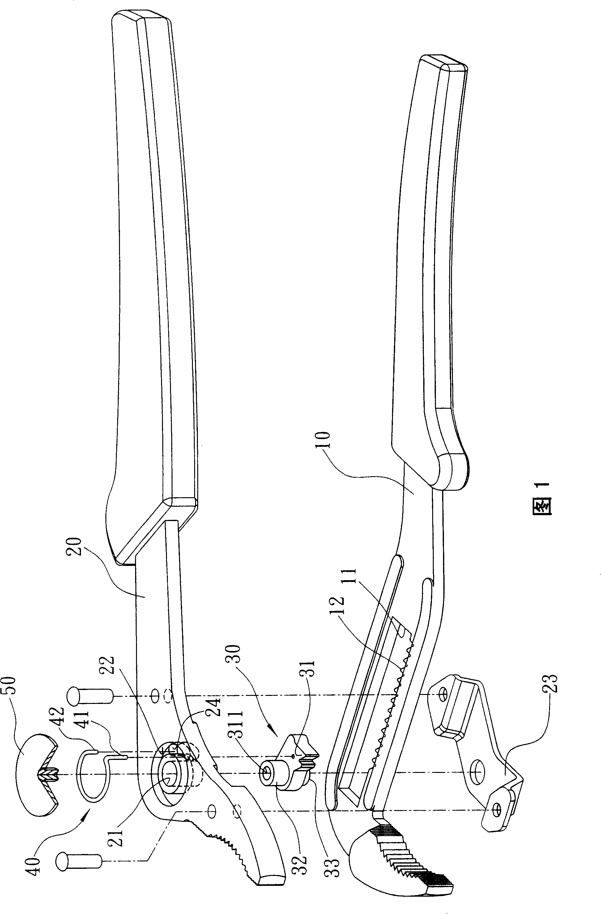
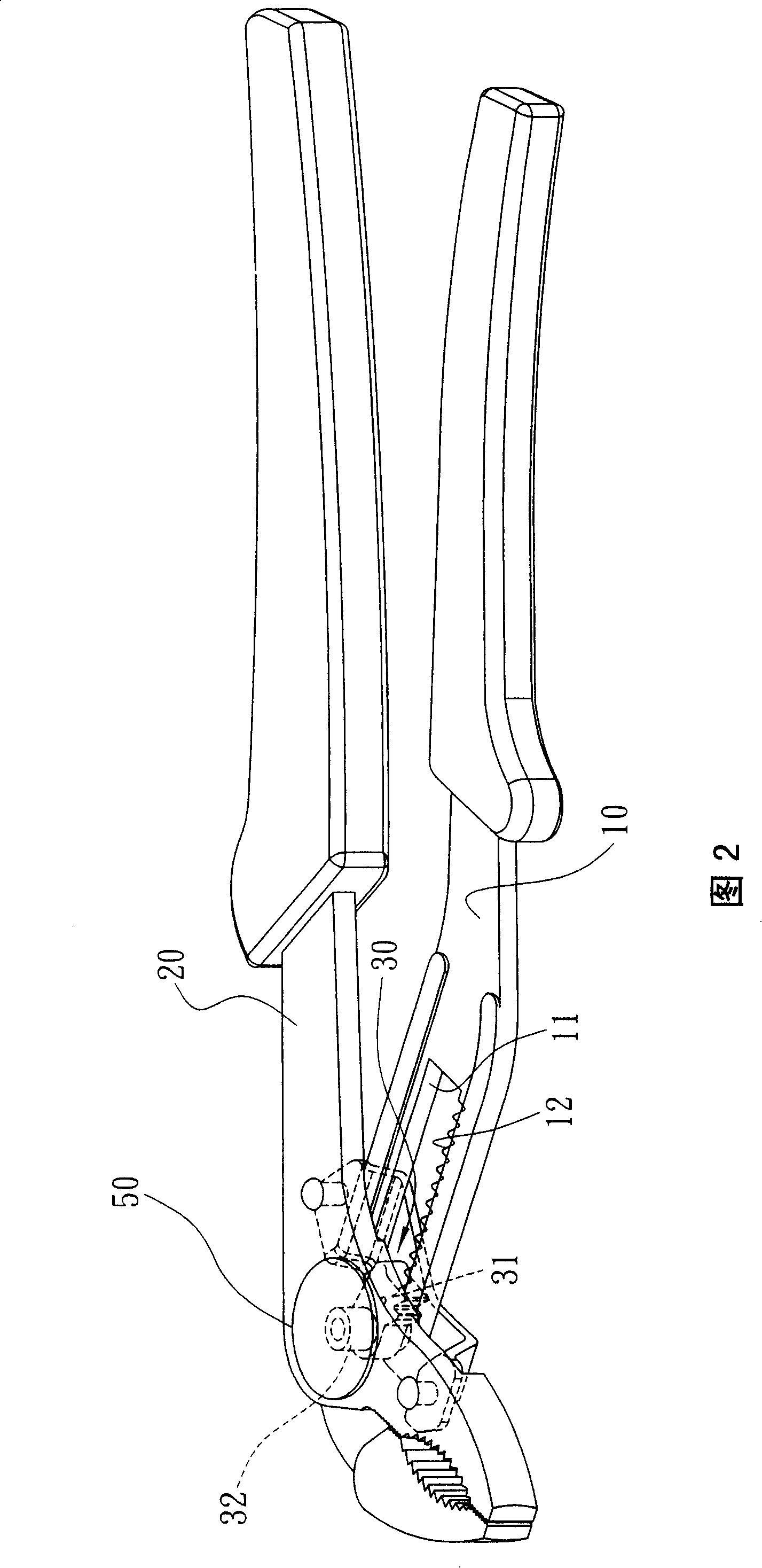
[0023] Referring to Fig. 1 and Fig. 2, a water pipe wrench structure mainly has a first pliers body 10 and a second pliers body 20, and the first pliers body 10 and the second pliers body 20 are articulated in a cross shape. , and the intersection of the first pliers body 10 and the second pliers body 20 is additionally provided with a long slot ...


PUM


Abstract

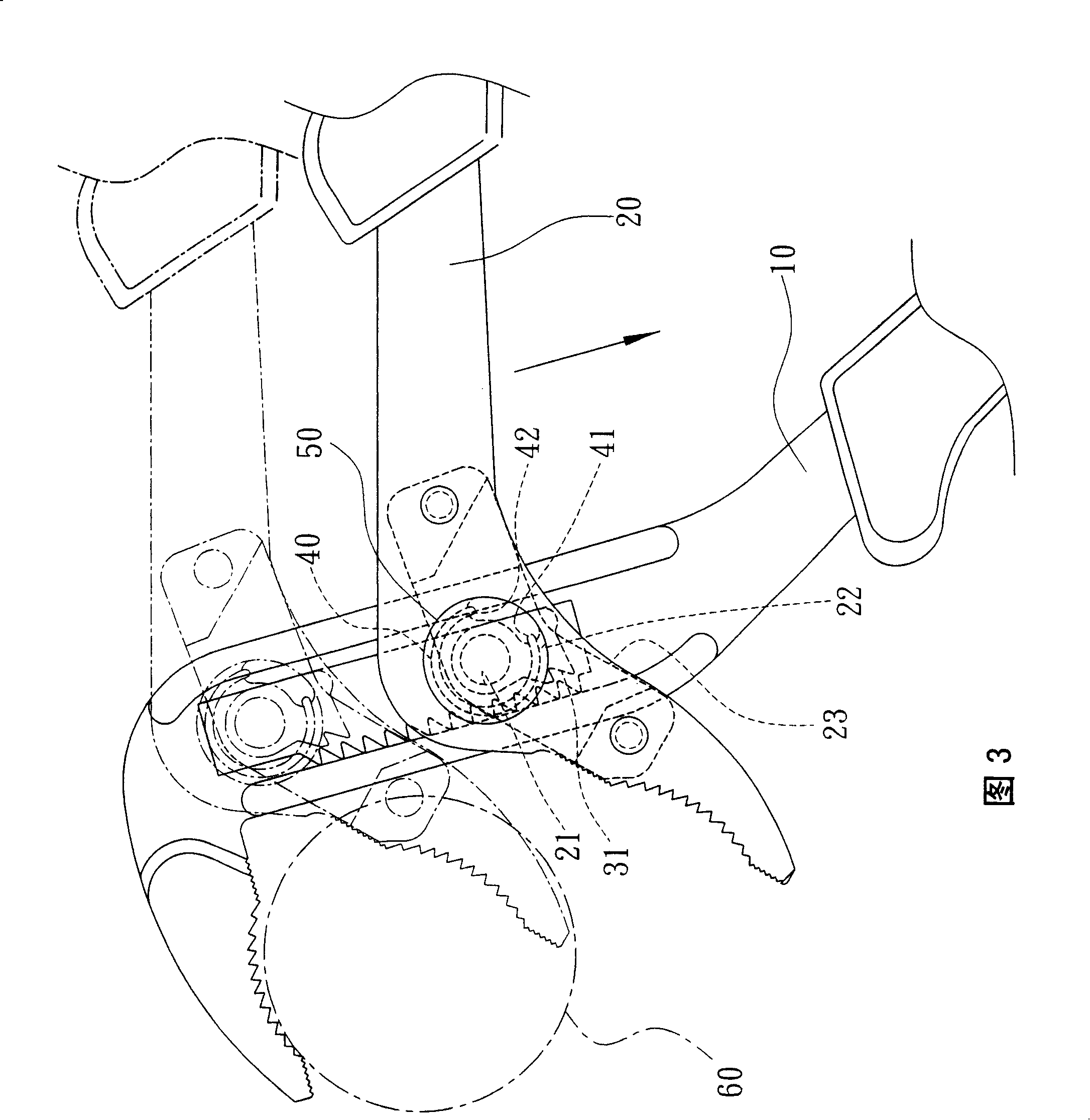
The invention provides a plumbing combination pliers structure, in particular to a first clamp body and a second clamp body which are crossly arranged; the first clamp body is provided with a long trough with a ratchet section; the second clamp body is connected with a ratchet block arranged in the long trough; furthermore, the ratchet block is connected with the second clamp body by a spring which is provided with a long edge and a short edge and is clamped by virtue of the ratchet block arranged in the long trough in order to fix the clamping angle; when the clamping angle is required to be adjusted, the second clamp body can be rotated to lead an arc hole thereof to drive the spring to rotatablely move and drive the ratchet part of the ratchet block to disconnect from the ratchet section, thus achieving the clamping angle formed by adjusting the second clamp body. Therefore, the invention is the plumbing combination pliers structure which can precisely and fast adjust clamping angle.

Description

technical field [0001] The present invention provides a water pipe wrench structure, especially a ratchet block that is accommodated in a long groove of the first pliers body to clamp the ratchet segment to fix the clamping angle, and drive the second pliers body to A spring is used to separate the ratchet portion of the ratchet block from the ratchet section, thereby achieving a water pipe wrench structure for adjusting the clamping angle formed by the two pliers. Background technique [0002] As shown in Figure 5, it is a commonly used water pipe wrench structure, which is mainly composed of a first pliers body 70 and a second pliers body 71 intersecting, wherein the intersection of the first pliers body 70 and the second pliers body 71 is provided with a semicircle The hole section 701, and the semicircular hole section 701 is composed of a plurality of semicircular holes 702 juxtaposed. The intersection of the second pliers body 71 and the first pliers body 70 protrudes ...

Claims


Application Information

Patent Timeline
Patent Type & Authority Applications(China)
IPC IPC(8): B25B13/50B25B13/22B25B23/00B25B7/04
Inventor 蔡丞章
Owner MYTOOLS ENTERPRISE
Learn More