Single salient pole permanent magnetic paster bias magnetic motor scheme

A permanent magnet and chip technology, applied in electrical components, electromechanical devices, magnetic circuit static parts, etc., can solve problems such as unsatisfactory manufacturability, and achieve the effect of reducing low-speed torque pulsation, reasonable design, and eliminating magnetic flux leakage

Inactive Publication Date: 2008-06-11
苏州扬名机电有限公司 +1
View PDF0 Cites 9 Cited by
  • Summary
  • Abstract
  • Description
  • Claims
  • Application Information

AI Technical Summary

Problems solved by technology

Compared with conventional permanent magnet motors in terms of specific power and specific torque, this kind of motor is not inferior, but the manufacturability is still not satisfactory
[0005] For ordinary permanent magnet motors that have been widely used in recent years,

Method used


Image

  • Single salient pole permanent magnetic paster bias magnetic motor scheme
  • Single salient pole permanent magnetic paster bias magnetic motor scheme
  • Single salient pole permanent magnetic paster bias magnetic motor scheme

Examples


Embodiment 1

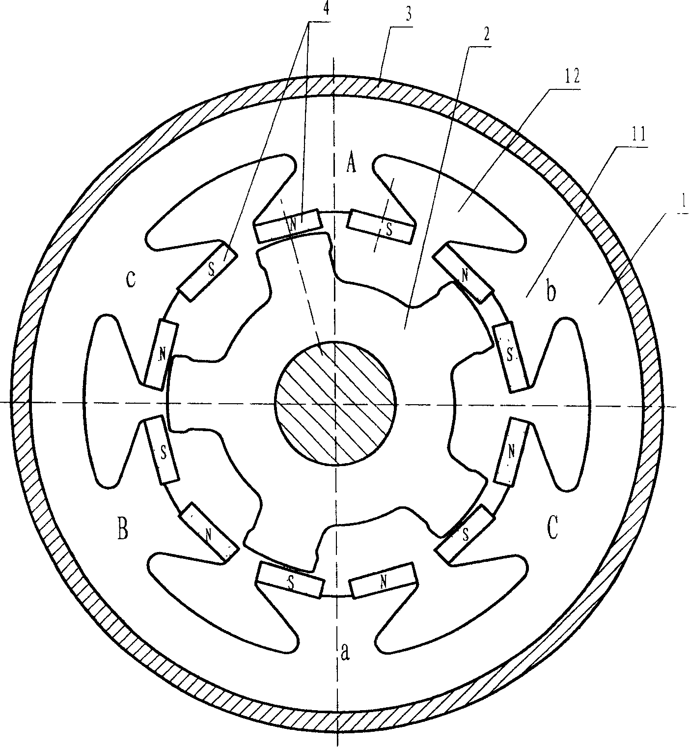
[0029] Example 1: Single-salient pole permanent magnet patch bias three-phase six-pole five-tooth motor

[0030] refer to figure 1 , among the figure (1) is the stator core, (11) is the stator pole, (12) is the line groove, (2) is the rotor, (3) is the shell, (4) is the permanent magnet.

[0031] There are 6 magnetic poles on the stator core as shown, and a pair of permanent magnets are pasted on each magnetic pole. The magnetization polarities of each adjacent permanent magnet are all opposite, and each piece of permanent magnet is evenly arranged on the circumference. In order to ensure that the sticking position of the permanent magnet is accurate, a small boss is designed in the middle of each magnetic pole. The stator winding can be single-span centralized or multi-span distributed.

[0032] figure 1 The rotor retains the salient pole structure of the traditional reluctance motor. The number of rotor teeth Z is equal to the logarithm of the stator permanent magnets 6, ...

Embodiment 2

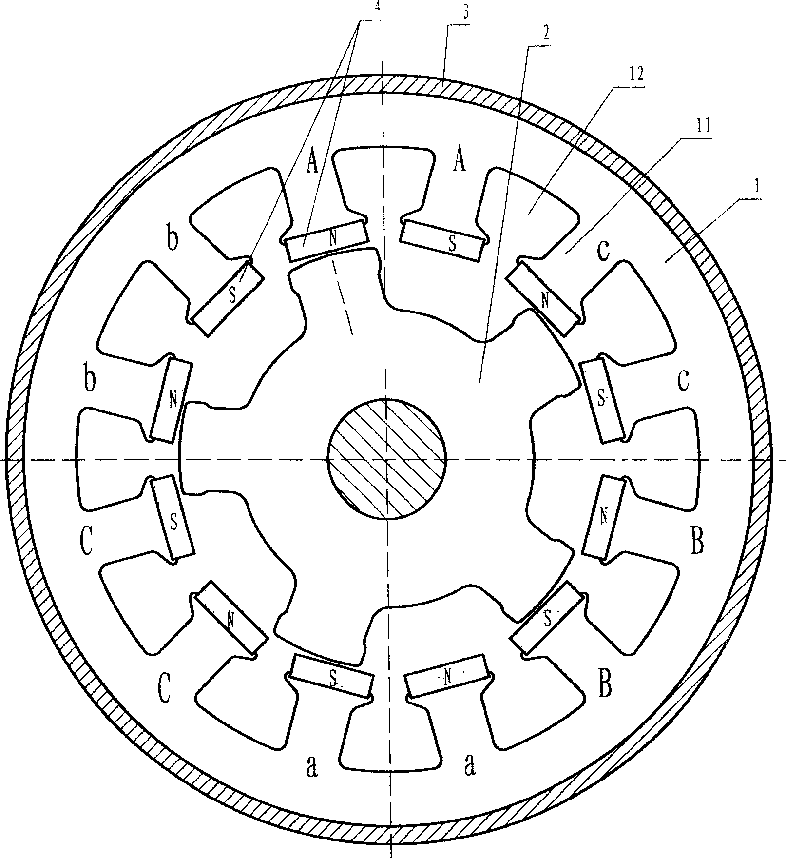
[0034] Embodiment 2: Single-salient pole permanent magnet patch bias three-phase twelve-pole five-tooth motor

[0035] refer to figure 2 , which is a schematic diagram of a three-phase, twelve-pole, five-tooth motor with a single-salient-pole permanent-magnet patch-bias bias.

[0036] figure 2 The stator core of the motor has 12 magnetic poles in total, and only one permanent magnet is pasted on each magnetic pole, and the magnetization polarity of adjacent permanent magnets is opposite; the rotor has 5 teeth. with the example figure 1 compared to, figure 2 only in figure 1 Basically, keep the position of the permanent magnet unchanged, divide each magnetic pole into two, and open a wire slot in the middle. figure 2 The pole distribution in the figure 1 It is basically the same. After doubling the capacity of the wire slot, the wiring is more flexible, which is conducive to the use of centralized windings with smaller spans, and is more conducive to the design of dis...

Embodiment 3

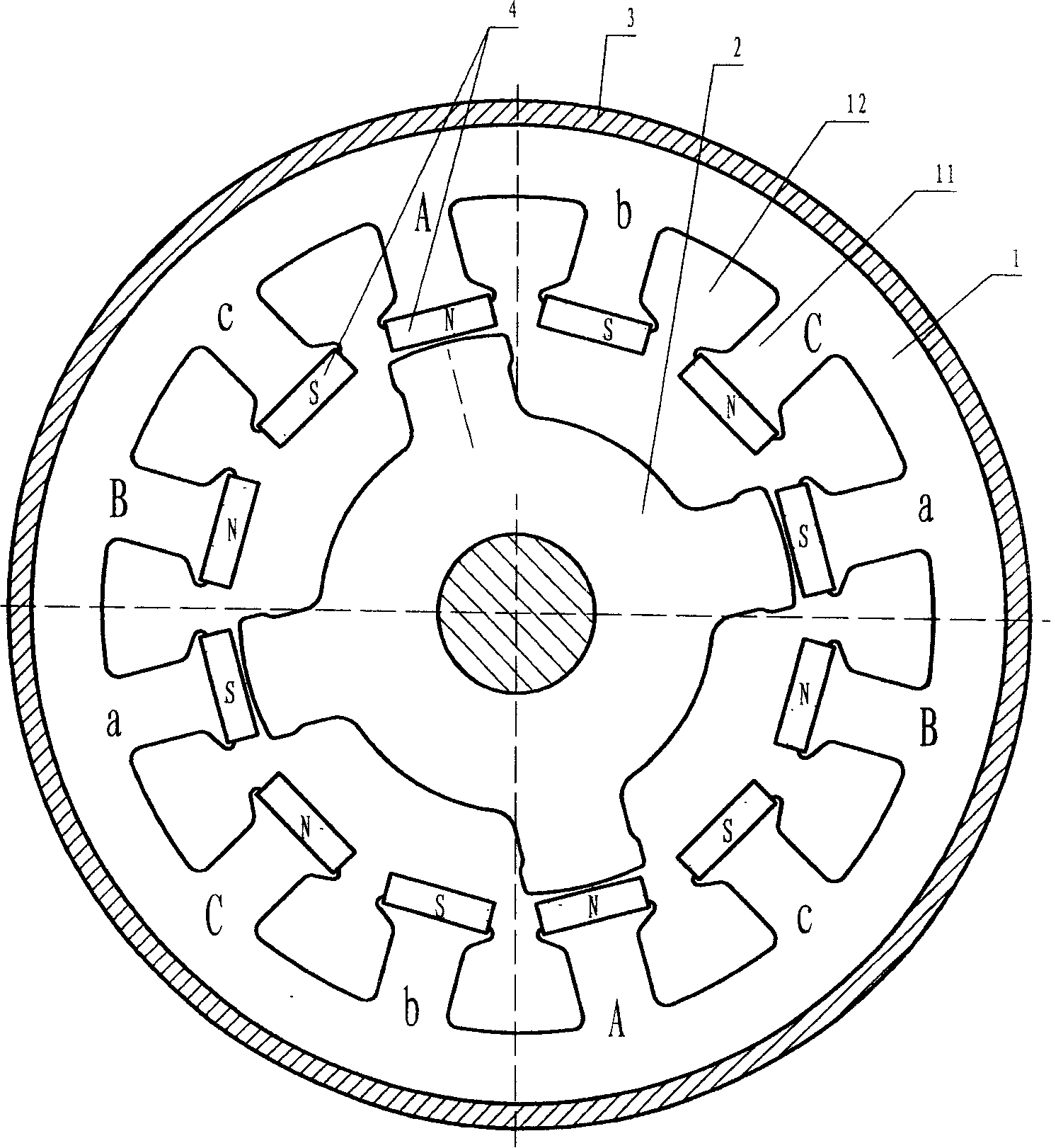
[0038] Embodiment 3: Single-salient pole permanent magnet patch bias three-phase twelve-pole four-tooth motor

[0039] refer to image 3 , the three-phase motor stator shown in the figure has 12 magnetic poles, and a permanent magnet is attached to each magnetic pole; the rotor has 4 teeth. From the point of view of mechanical structure, this example is similar to figure 2 The stator is the same, only the phase sequence arrangement of the magnetic poles is different. figure 2 The arrangement of the 4 magnetic poles of each phase is: every two adjacent magnetic poles form a group, and the two groups are arranged opposite to each other; image 3 The 4 magnetic poles of each phase are: each magnetic pole occupies a corner and is evenly distributed. image 3 This arrangement of magnetic poles makes the calculation method of the number of teeth of the rotor different, and the difference between the number of rotor teeth and the number of magnetic pole pairs is equal to the num...


PUM


Abstract

The invention relates to a monosalient pole permanent magnet patch magnetic bias motor proposal, and is characterized in that rotors retain the salient pole structure which is common in reluctance motors; permanent magnets are pasted in sequence along the circumferential direction in air gap surface of stator core. Similar to changing rotors of common permanent magnet motor to reluctant rotors, and moving permanent magnet from rotors to stators, the invention provides a new type motor.The invention refers to the magnetic steel surface pasting technique of common permanent magnet motor, combines magnetic bias principle of main circuit and cogging magnetic bias reluctance motor, and has the advantages of advanced technique and good manufacturability. As no magnetic steel is pasted on rotors, the new type motor is more suitable for high speed rotation situation. Combined with driving control circuit, the switched magnetic bias speed control motor system has wide range of variable-speed and food performance price ratio.

Description

Technical field: [0001] The invention belongs to the electromechanical field, and in particular relates to an improvement of a bias reluctance motor, in particular to a single salient pole permanent magnet patch bias motor solution. Background technique: [0002] The structure of the reluctance motor is basically the same as that of the ordinary motor, including the stator, the rotor and the supporting shell. The difference is that the rotor of the reluctance motor is usually non-magnetic. The pole rotor generates suction, which drives the rotor to rotate. [0003] The biased reluctance motor works hard on the stator, strips the DC component of the drive current from it, and replaces it with permanent magnet or excitation method, which is called transverse bias, which effectively reduces the apparent drive power and reduces the cost of the drive circuit. And make it compatible with other motor drive circuits, creating a favorable condition for the wide application of reluct...

Claims


Application Information

Patent Timeline
IPC IPC(8): H02K1/17H02K15/03H02K37/02H02K37/10
Inventor 朱正风
Owner 苏州扬名机电有限公司
Why Eureka
Try Eureka