Single protrusion permanent magnetic motor scheme

A technology of permanent magnet motor and salient pole, which is applied in the direction of electrical components, electromechanical devices, magnetic circuit rotating parts, etc., can solve problems such as unsatisfactory manufacturability, achieve low-speed torque ripple reduction, eliminate magnetic flux leakage, and unique structure Effect

Inactive Publication Date: 2008-08-06
苏州扬名机电有限公司 +1
View PDF0 Cites 6 Cited by
  • Summary
  • Abstract
  • Description
  • Claims
  • Application Information

AI Technical Summary

Problems solved by technology

Compared with conventional permanent magnet motors in terms of specific power and specific torque, this kind of motor is not inferior, but the manufacturability is still not satisfactory

Method used


Image

  • Single protrusion permanent magnetic motor scheme
  • Single protrusion permanent magnetic motor scheme

Examples


Embodiment 1

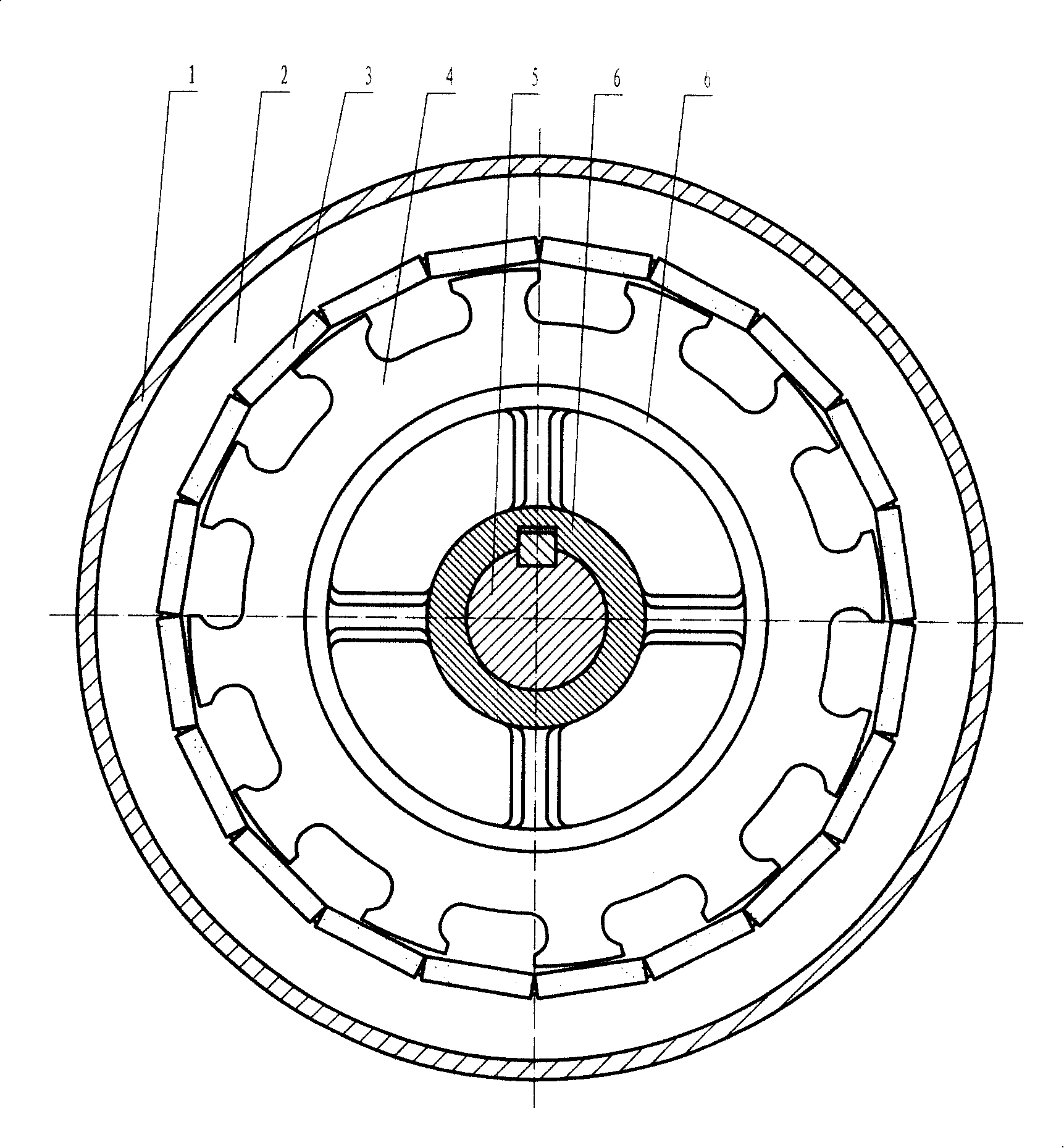
[0029] Embodiment 1: Single salient pole three-phase four-pole external rotor permanent magnet motor

[0030] refer to figure 1 In the figure, the inner stator core (2) is sleeved on the stator support (6), and there is a fixed shaft (5) in the middle of the stator support (6); the rotor core (4) is installed on the rotatable casing (1), and the iron The inside of the core is pasted with a permanent magnet (3). figure 1 The motor stator has twelve magnetic poles, which are divided into three phases, and each phase has four magnetic poles; the rotor has twenty permanent magnets, and every two adjacent permanent magnets are arranged in opposite polarities, and the magnetization direction is perpendicular to the surface of the air gap.

[0031] Compared with the conventional permanent magnet motor, the motor shown is only half of the stator poles. If the conventional motor principle is used, the motor should be called a 20-pole motor, but this is a reluctance motor, which is a t...

Embodiment 2

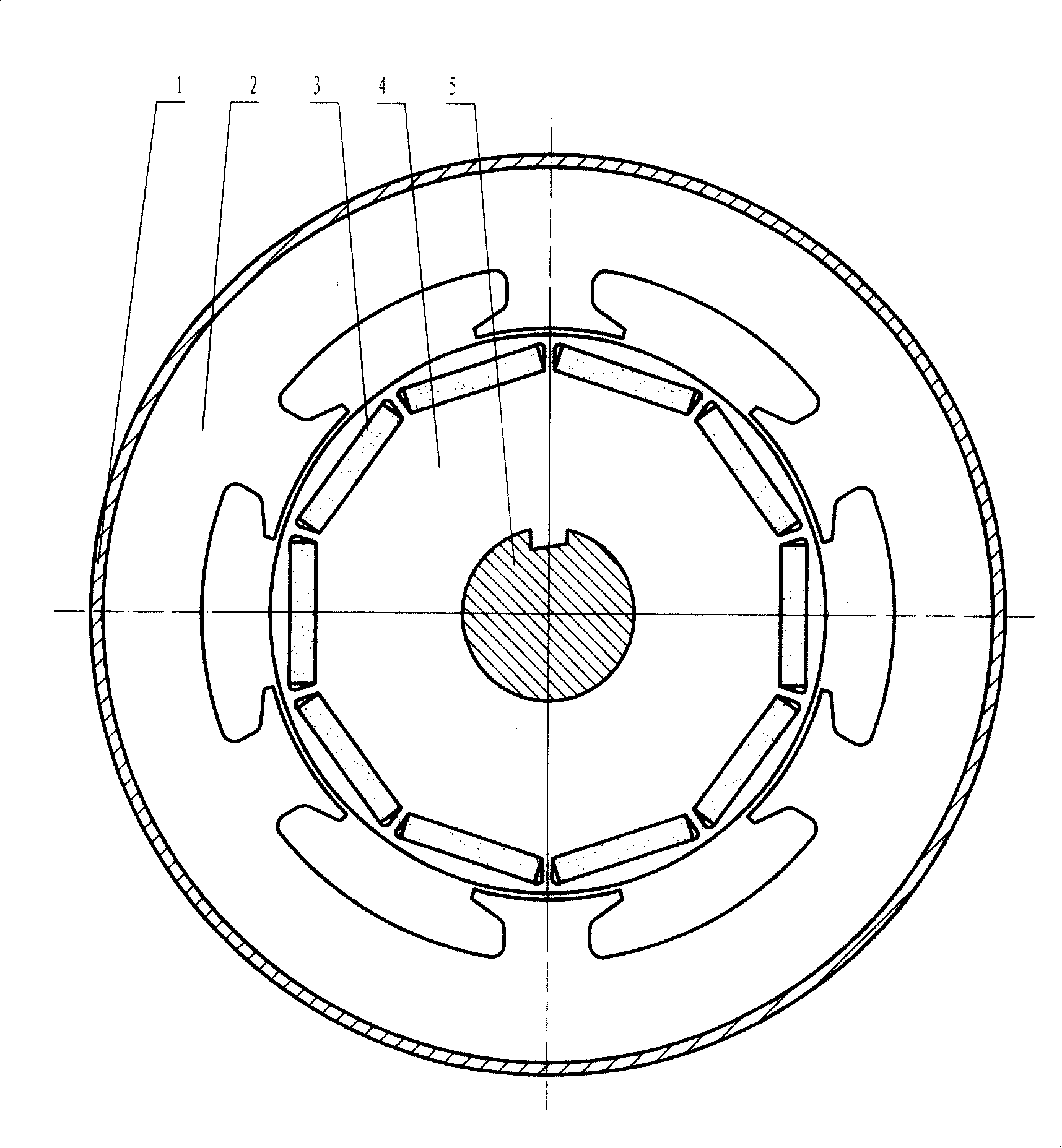
[0033] Embodiment 2: Single-salient pole three-phase two-pole inner rotor permanent magnet motor

[0034] refer to figure 2 , which is a schematic diagram of a single-salient-pole three-phase two-pole inner-rotor permanent magnet motor, and the leading marks in the figure are the same as those in Embodiment 1. In the figure, the outer stator core (2) is contained in the casing (1), the rotor core (4) is contained on the rotating shaft (5), and the rotor core is inlaid with a permanent magnet (3). figure 2 The stator of the motor has six magnetic poles, which are divided into three phases, and each phase has two magnetic poles; the rotor has ten permanent magnets, and every two adjacent permanent magnets are arranged in opposite polarities, and the magnetization direction is perpendicular to the surface of the air gap.

[0035] Compared with Example 1, this example is only different in the difference between the inner and outer rotors and the way the permanent magnets are fi...


PUM


Abstract

The invention relates to a single salient pole permanent magnet motor scheme, which is characterized in that: a stator keeps a salient pole structure which is often used in a general magnetic resistance motor; permanent magnets are orderly and fully embedded in a rotor core along the circumferential direction of an air gap; a novel motor is formed by similarly changing the stator of the general permanent magnet motor into the salient pole type magnetic resistance stator; by adopting the magnetic biasing theory of a major loop and a tooth socket magnetic biasing type magnetic resistance motor and referring to the permanent magnet rotor structure of the general permanent magnet motor, the single salient pole permanent magnet motor scheme has the characteristics of advanced technique and good manufacturability; moreover, because the invention can make a stator trunking and a notch bigger, thereby facilitating to the winding of a winding machine on the one hand and being capable of adopting the multi-span winding of the magnetic biasing motor on the other hand; as a result, the number of turns of each trunking are reduced times, and the consumption of copper wires is greatly reduced.

Description

Technical field: [0001] The invention belongs to the electromechanical field, and in particular relates to an improvement of a biased reluctance motor, especially a single salient pole permanent magnet motor solution. Background technique: [0002] The structure of the reluctance motor is basically the same as that of the ordinary motor, including the stator, the rotor and the supporting shell. The difference is that the traditional reluctance motor usually does not have permanent magnets. The pole rotor generates suction, which drives the rotor to rotate. This type of motor is also known as a doubly salient motor. [0003] The biased reluctance motor works hard on the excitation magnetic field component, strips the DC component of the drive current that generates the magnetomotive force, and replaces it with permanent magnet or excitation method, which is called transverse bias, which effectively reduces the apparent drive power. The cost of the drive circuit is reduced a...

Claims


Application Information

Patent Timeline
Patent Type & Authority Applications(China)
IPC IPC(8): H02K3/18H02K1/27H02K15/02H02K37/14
Inventor 朱正风
Owner 苏州扬名机电有限公司
Why Eureka
Try Eureka