Customer replaceable unit assembly

A technology that replaces units and users, and is applied in the directions of object supply, electrical recording process applying charge pattern, equipment for electrical recording process applying charge pattern, etc.

Inactive Publication Date: 2012-09-26
XEROX CORP
View PDF0 Cites 0 Cited by
  • Summary
  • Abstract
  • Description
  • Claims
  • Application Information

AI Technical Summary

Problems solved by technology

Such pinch lines and / or flat spots are believed to be the cause of early retard roll flat spots and roll noise during operation, in either case leading to premature failure

Method used


Image

  • Customer replaceable unit assembly
  • Customer replaceable unit assembly
  • Customer replaceable unit assembly

Examples


Embodiment Construction

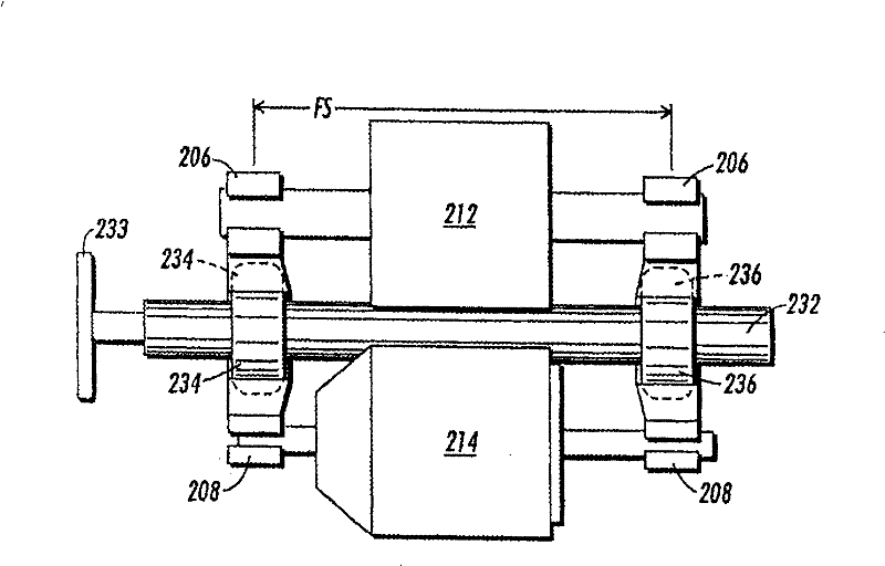
[0012] now refer to figure 1 , shows a customer replaceable unit (CRU) frame 202 for the continuous paper nip assembly mounted (without nip forming rollers thereto) in cavity 120 of section 110 of paper processing machine 100. For example, the machine may be a xerographic copier, and the feed unit may be a CRU such as a compact document feeder. The fit of the CRU frame 202 in the cavity 120 is such that even with nip forming rollers fitted thereto, the feeder assembly will operate in such a section without obstructing any other adjacent machines part. as in figure 2 As illustrated in , the CRU frame 202 is designed such that when the feed roller 212 and the feed roller 214 are assembled thereon, one roller contacts the other to form the feed nip 216 .

[0013] now refer to all Figure 1 to Figure 5 , illustrating details of a paper feeder assembly such as a customer replaceable unit (CRU) assembly 200 of the present specification. The CRU assembly 200 is equally suitable...


PUM


Abstract

The invention discloses a CRU assembly arranged in a paper processor, comprising (a) a CRU frame with the size of a frame and used for being assorted in the mounting part inside the paper processor; (b) a first roller rotatablely assembled on the CRU frame; (c) a second roller rotatablely assembled on the CRU frame and used for elastically contacting with the first roller so as to form a paper feeder; and (d) an isolator and a reverse-mounting assembly, which comprise (i) a holding mechanism formed inside the CRU frame and (ii) a movable component mounted inside the holding mechanism and usedfor temporarily prevent the CRU frame from being assembled inside the mounting part in the paper processor and temporarily isolating the second roller so that the second roller is released from the elastic contact with the first roller, thereby avoiding the flat points of roller, the noise due to the operation of the roller and the premature roller failure.

Description

technical field [0001] This specification relates to customer replaceable units (CRUs) of sheet handling machines, such as xerographic copiers, and more particularly to user replaceable units (CRUs) for use during storage and shipping, but after placing the feeder feed assembly or CRU on the machine. A device that prevents undesired deformation in either of the two rollers of the feeder nip assembly such as the retard roller and the feed roller of the document feeder CRU after assembly. Background technique [0002] In a typical xerographic printer using the xerographic process, the photoconductive element is charged to a substantially uniform potential such that its surface becomes susceptible. The charged portion of the photoconductive element is exposed to a light image of an original document that is either manually placed on the machine's platen or automatically fed onto such a platen by the machine's document processor. Exposure of the charged photoconductive element ...

Claims


Application Information

Patent Timeline
Patent Type & Authority Patents(China)
IPC IPC(8): G03G15/00B65H5/06
CPCG03G21/1695G03G2221/1807G03G15/65
Inventor J·F·伦巴多S·J·普罗维登扎
Owner XEROX CORP
Why Eureka
Try Eureka