Method and apparatus for system maintenance

A technology for system maintenance and acquisition of systems, applied in transmission systems, digital transmission systems, electrical components, etc., can solve problems such as the lack of means for NMS to maintain EMS systems, and achieve the effect of improving centralization and improving efficiency

Active Publication Date: 2011-06-22
SHANGHAI MUNICIPAL ELECTRIC POWER CO
View PDF0 Cites 0 Cited by
  • Summary
  • Abstract
  • Description
  • Claims
  • Application Information

AI Technical Summary

Problems solved by technology

[0006] The present invention aims to solve the technical problem that the existing network management interface technology lacks the means for maintaining the EMS system by the NMS. Therefore, the main purpose of the present invention is to provide a system maintenance mechanism

Method used


Image

  • Method and apparatus for system maintenance
  • Method and apparatus for system maintenance
  • Method and apparatus for system maintenance

Examples


no. 1 example

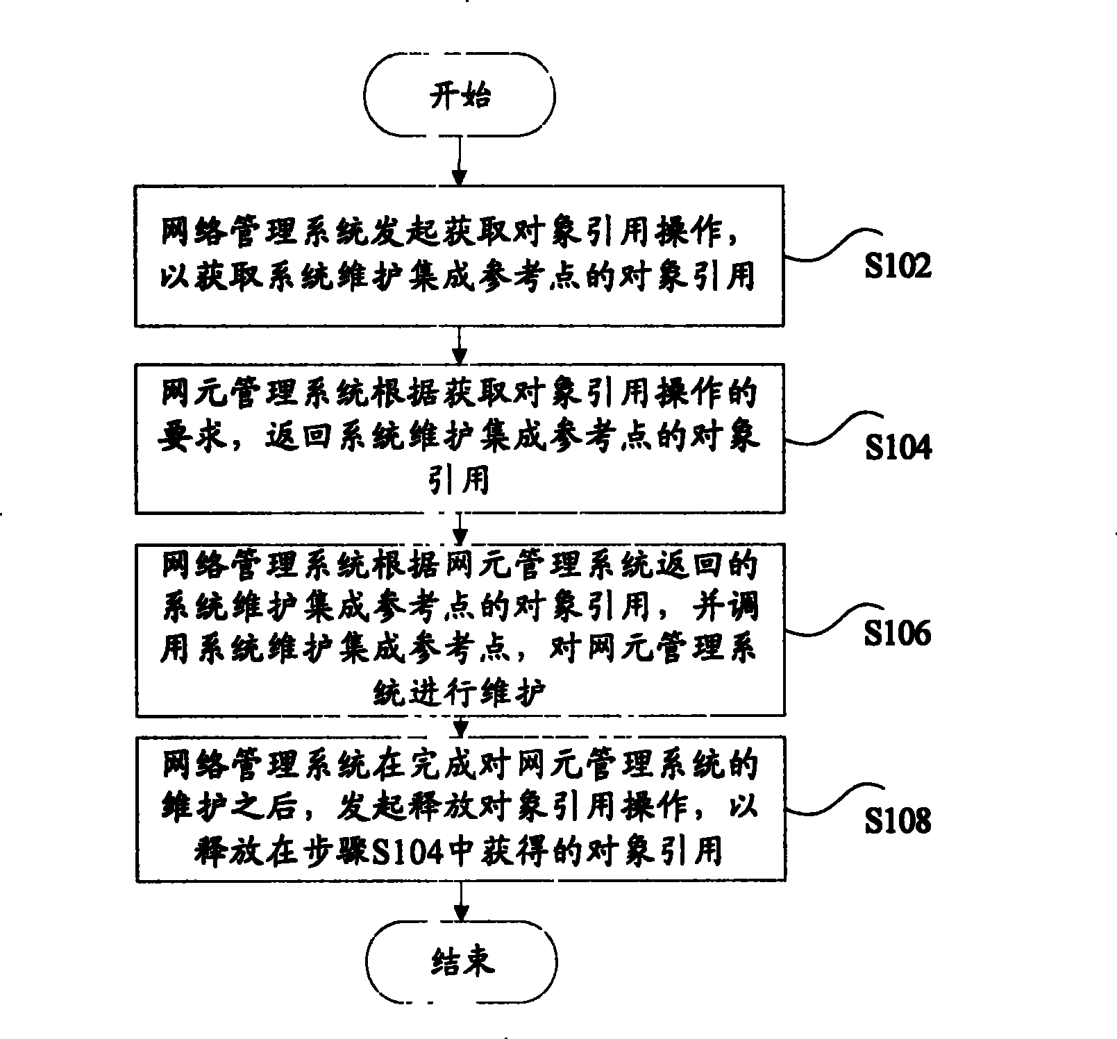
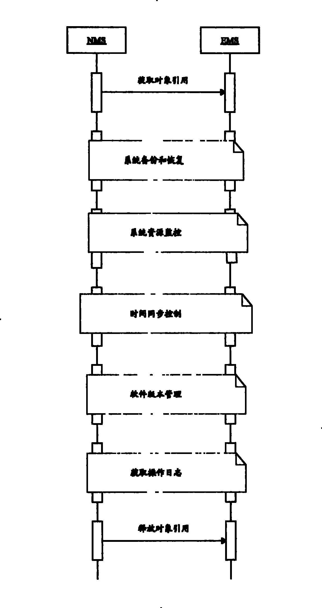
[0022] first refer to figure 1 and figure 2 A first embodiment of the present invention is described. figure 1 is a flowchart of a system maintenance method according to an embodiment of the present invention, figure 2 is a schematic diagram of a system maintenance method according to an embodiment of the present invention.

[0023] Such as figure 1 As shown, the method includes the following steps: step S102, the network management system initiates an object reference acquisition operation to obtain the object reference of the system maintenance integration reference point; step S104, the network element management system returns to the system maintenance according to the requirements of the object reference acquisition operation Integrating the object reference of the reference point; step S106, the network management system according to the object reference of the system maintenance integration reference point returned by the network element management system, and call...

no. 2 example

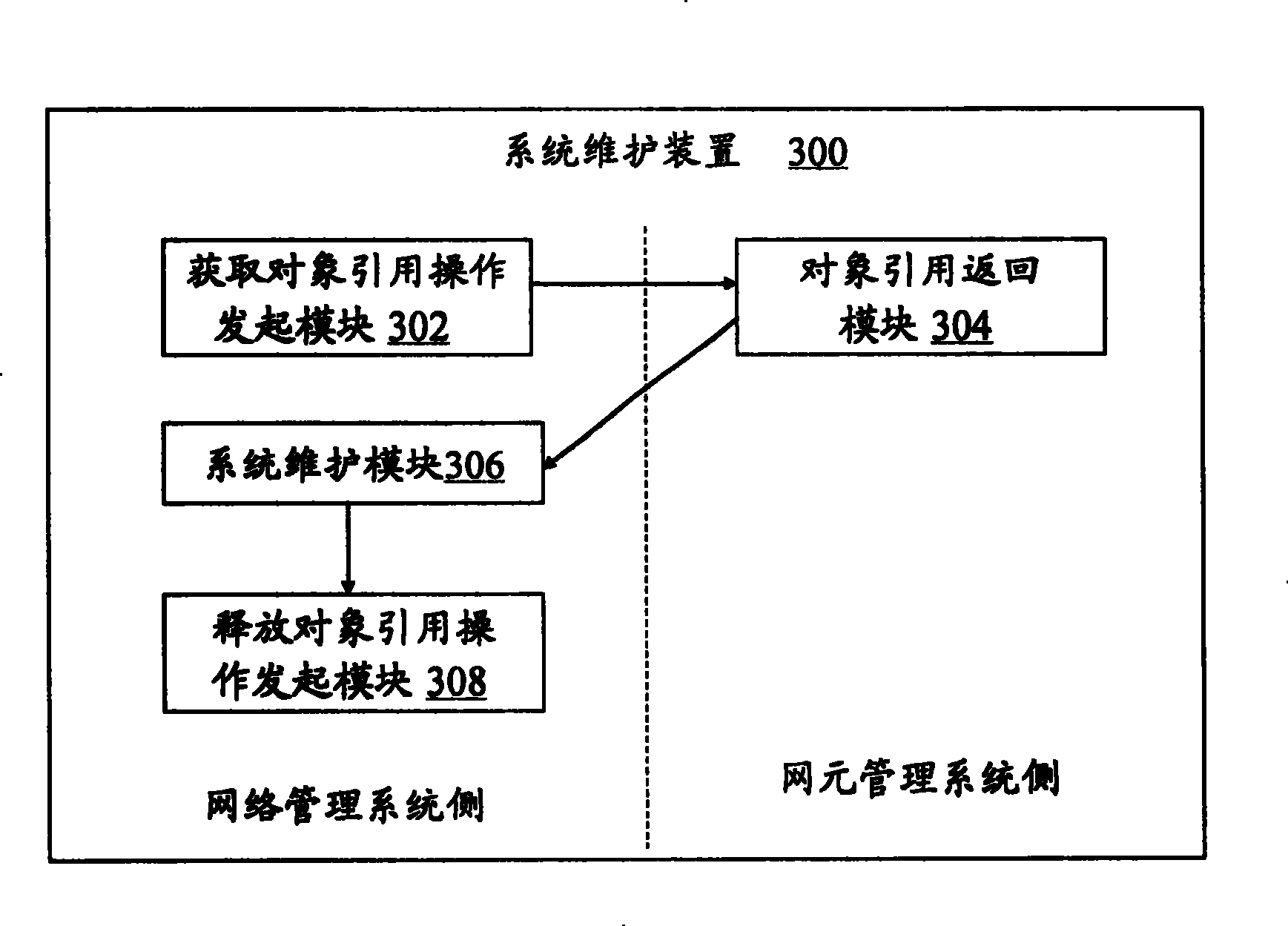
[0032] The following will refer to image 3 A second embodiment of the present invention is described. image 3 is a block diagram showing the configuration of the system maintenance apparatus 300 according to the second embodiment of the present invention.

[0033] Such as image 3 As shown, the device includes: an object reference acquisition operation initiating module 302, located at the network management system side, for initiating an object reference acquisition operation to obtain the object reference of the system maintenance integration reference point; an object reference returning module 304, located at the network element management The system side is used to return the object reference of the system maintenance integration reference point according to the requirement of obtaining the object reference operation; the system maintenance module 306 is located on the network management system side and is used to return the system maintenance integration reference poi...


PUM


Abstract

The invention discloses a system maintenance method. The method includes the following steps: step one, a network management system launches the operation of acquiring the object reference, so as to acquire the object reference of an integrated reference point for the system maintenance; step two, a network element management system returns to the object reference of the integrated reference point for the system maintenance according to the requirement for the operation of acquiring the object reference; step three, the network management system carries through maintenance on the network element management system according to the object reference of the integrated reference point for the system maintenance returned by the network element management system and transfers the integrated reference point for the system maintenance; and step four, the network management system launches the operation of releasing the object reference after finishing the maintenance on the network element management system, so as to release the object reference acquired in the step two. Besides, the invention also discloses a system maintenance device. By using the invention, the centralized and automation managements on the network can be improved by the network management system, thereby improving the management efficiency.

Description

technical field [0001] The present invention relates to the communication field, and in particular, relates to a system maintenance method and device between network management interfaces, which are used for a network management system to maintain a network element management system. Background technique [0002] The interface between the network management system (NMS) and the network element management system (EMS) is called Itf-N interface. EMS mainly completes the network element management layer (EML) function in ITU TMN, that is, completes the management function of one or more mobile communication devices. Usually, EMS between different equipment suppliers cannot be used universally. NMS mainly completes the network management layer (NML) function in ITU TMN, and is responsible for the management of all network elements in a managed network. For the situation that there are multiple equipment suppliers in the managed network (called a subnet), the purpose of managing...

Claims


Application Information

Patent Timeline
Patent Type & Authority Patents(China)
IPC IPC(8): H04L12/24
Inventor 熊康建黄树强沈毅
Owner SHANGHAI MUNICIPAL ELECTRIC POWER CO
Why Eureka
Try Eureka