Backlight module

A backlight module and conductive sheet technology, applied in optics, nonlinear optics, instruments, etc., can solve the problems of easy breakage of lamp wires and complicated assembly of backlight modules, and achieve the effect of overcoming breakage of lamp wires and simple assembly.

Inactive Publication Date: 2010-04-14
INNOCOM TECH (SHENZHEN) CO LTD +1
View PDF5 Cites 0 Cited by
  • Summary
  • Abstract
  • Description
  • Claims
  • Application Information

AI Technical Summary

Problems solved by technology

[0008] In order to solve the problem of complex assembly of backlight modules in the prior art and easy breakage of lamp wires, it is necessary to provide a backlight module that is simple to assemble and can effectively overcome the problem of lamp wire breakage

Method used


Image

  • Backlight module
  • Backlight module
  • Backlight module

Examples


Embodiment Construction

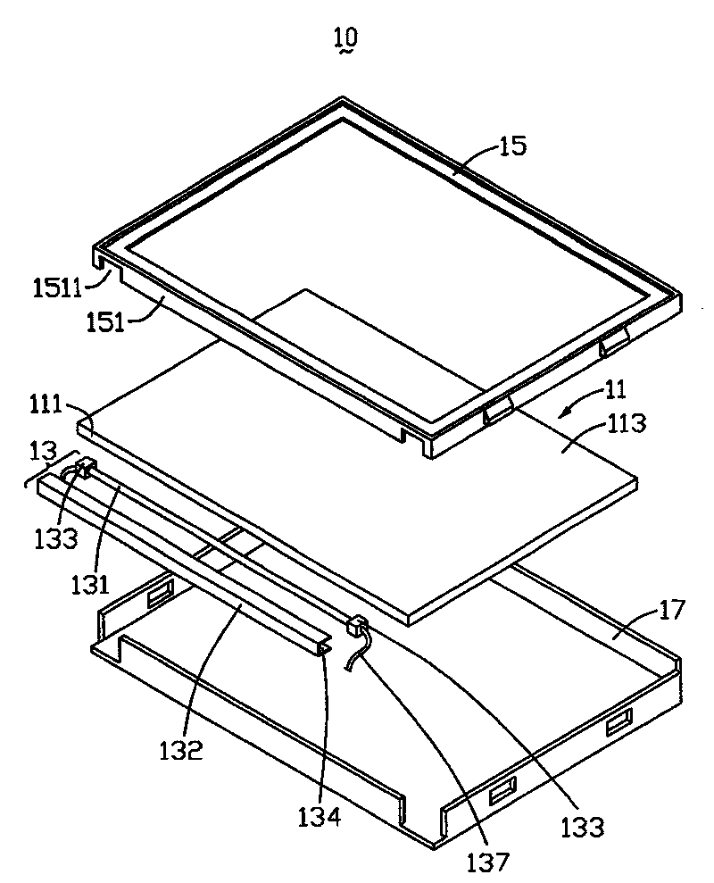
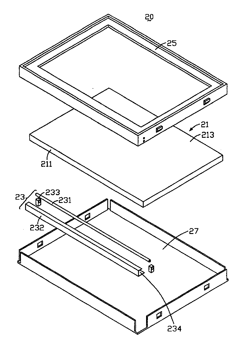
[0019] see image 3 , is a three-dimensional exploded schematic view of a preferred embodiment of the backlight module of the present invention. The backlight module 20 includes a bottom plate 27 , a lamp set 23 , a light guide plate 21 and a frame 25 . The bottom plate 27 cooperates with the frame 25 to accommodate the light guide plate 21 and the light tube set 23 .

[0020] The light guide plate 21 includes a light incident surface 211 and a light exit surface 213 adjacent to the light incident surface 211 . The light tube set 23 includes a light tube 231 , a light tube cover 232 surrounding the light tube 231 , and holding rubber sleeves 233 respectively sleeved on two ends of the light tube 231 . The lamp cover 232 has an opening 234 facing the light incident surface 211 of the light guide plate 21 .

[0021] see Figure 4 and Figure 5 , Figure 4 yes image 3 A three-dimensional schematic diagram of the frame 25 of the backlight module 20 flipped and rotated 90 d...


PUM


Abstract

The invention relates to a backlight module, which comprises a framework and a lamp tube; wherein the framework is provided with a first conductive structure and a second conductive structure which contact two ends of the lamp tube respectively. The two conductive structures are used to connect with a power source, so as to supply power for the lamp tube.

Description

technical field [0001] The invention relates to a backlight module. Background technique [0002] Since the liquid crystal in the liquid crystal panel itself does not have luminous properties, in order to achieve the display effect, it is necessary to provide a surface light source device for the panel of the liquid crystal display device, such as a backlight module, whose function is to supply a surface light source with sufficient brightness and uniformity to the liquid crystal panel. [0003] Usually, the light source of the backlight module needs to use an external power supply. Therefore, in the process of assembling the backlight module, after the light source is embedded, the power cord of the external power supply must be drawn out for subsequent use. [0004] see figure 1 , is a three-dimensional exploded schematic diagram of a backlight module in the prior art. The backlight module 10 includes a bottom plate 17 , a lamp set 13 , a light guide plate 11 and a plast...

Claims


Application Information

Patent Timeline
Patent Type & Authority Patents(China)
IPC IPC(8): G02F1/1335G02F1/1333G02F1/133G09F9/35
Inventor 景小红
Owner INNOCOM TECH (SHENZHEN) CO LTD
Why Eureka
Try Eureka