Movable hoisting device supporting leg and movable hoisting device with the supporting leg

A mobile lifting and lifting equipment technology, applied in the direction of cranes, etc., can solve problems such as downward bending, oil cylinder failure, and manufacturing difficulties, and achieve the effect of reducing the subsidence of lifting equipment, reducing the degree of subsidence, and reducing failure

Inactive Publication Date: 2008-07-16
SANY AUTOMOBILE HOISTING MACHINERY
View PDF0 Cites 5 Cited by
  • Summary
  • Abstract
  • Description
  • Claims
  • Application Information

AI Technical Summary

Problems solved by technology

[0004] However, the above-mentioned L-shaped legs also have obvious disadvantages
[0005] First of all, after the horizontal extension beam 1-1 of the above-mentioned L-shaped leg is loaded, the direction of the force it receives is perpendicular to the extension direction of the horizontal extension beam 1-1, so that the horizontal extension arm 1-1 of the leg when lifting 1 produces a large bending stress, and the horizontal extension beam 1-1 will bend downward significantly, causing the overall body to sag
Moreover, since the force of the supporting legs 1-2 in the vertical direction acts on one side in ...

Method used


Image

  • Movable hoisting device supporting leg and movable hoisting device with the supporting leg
  • Movable hoisting device supporting leg and movable hoisting device with the supporting leg

Examples


Embodiment Construction

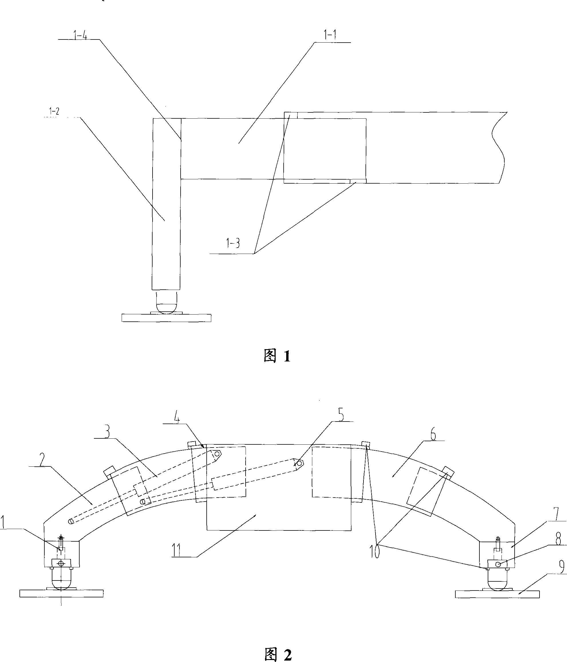
[0029] Please refer to FIG. 2 , which shows a structural view of the legs of the movable lifting device provided by the embodiment of the present invention. The structure of the outrigger is left-right symmetrical, and only the names of the parts on one side are marked in the figure, and the parts on the other side are mentioned with the same names and labels.

[0030] As shown in the figure, on the vehicle frame 11, a fixed leg box 4 is fixed thereon by welding or other means, and the fixed leg box 4 is a hollow box-shaped structure, which protrudes from the vehicle frame 11 to provide Fixed foundation.

[0031] The first-level movable leg section 6 is socketed in the fixed leg box 4, and the first-level movable leg section 6 is an arc-shaped hollow box whose outer periphery matches the inner periphery of the fixed leg box 4, and can be The box body of described fixed leg box 4 expands and contracts. In this primary movable leg section 6, the secondary movable leg section 2...


PUM


Abstract

The invention discloses an outrigger of a movable lifting device; the outrigger comprises a movable outrigger joint with at least one expandable level; the expansion direction of each level of movable outrigger joint has a downward inclining angle; outrigger joints are symmetrically arranged on the lifting device to form an arc support for the lifting device. The invention also provides a lifting device, correspondingly arranging the outrigger of the movable lifting device. Compared with the prior art, the invention provides the outrigger of the movable lifting device to provide the arc support for the lifting device. The arc support can prevent the vertical pressure on the outrigger by a load of the lifting device from concentrating on some special positions, and lighten the downward sinking of the lifting device caused by applying a horizontal vertical L-shaped outrigger in the prior art.

Description

technical field [0001] The invention relates to lifting equipment technology, in particular to a movable lifting equipment support leg. The present invention also provides a movable lifting device with the above outrigger. Background technique [0002] In various construction, loading and unloading occasions, lifting equipment is widely used. Large and movable lifting equipment such as cranes all have multiple outriggers, and the effect of the outriggers is to provide support for the lifting equipment when the lifting equipment performs lifting operations. These outriggers are capable of rotating and telescoping, and when the lifting equipment needs to move, the outriggers retract into a moving position without providing support. When the lifting equipment is used for lifting operations, the outriggers are extended to support the ground, providing support for the lifting equipment and increasing the supporting area of ​​the crane. The above functions prevent the lifting e...

Claims


Application Information

Patent Timeline
IPC IPC(8): B66C23/80
CPCB66C23/80
Inventor 赵信毅曾小雄李利
Owner SANY AUTOMOBILE HOISTING MACHINERY
Why Eureka
Try Eureka