Distributed arithmetic logic unit security check

A technology of arithmetic logic unit and control module, which is applied in the direction of registration/indication of vehicle operation, registration/instruction, instrument, etc., and can solve the problems of increasing the cost of production control module 10

Inactive Publication Date: 2008-07-16
GM GLOBAL TECH OPERATIONS LLC
View PDF0 Cites 2 Cited by
  • Summary
  • Abstract
  • Description
  • Claims
  • Application Information

AI Technical Summary

Problems solved by technology

Providing a secondary processor increases the

Method used


Image

  • Distributed arithmetic logic unit security check
  • Distributed arithmetic logic unit security check
  • Distributed arithmetic logic unit security check

Examples


Embodiment Construction

[0017] The following description is merely exemplary in nature and is not intended to limit the disclosure, application, or uses. It should be understood that throughout the drawings, corresponding reference numerals indicate like or corresponding parts and features. As used herein, the term module refers to an application-specific integrated circuit (ASIC), an electronic circuit, a processor (shared, dedicated, or clustered) and memory, combinational logic, that executes one or more software or firmware programs circuits and / or other suitable components that provide the described functionality.

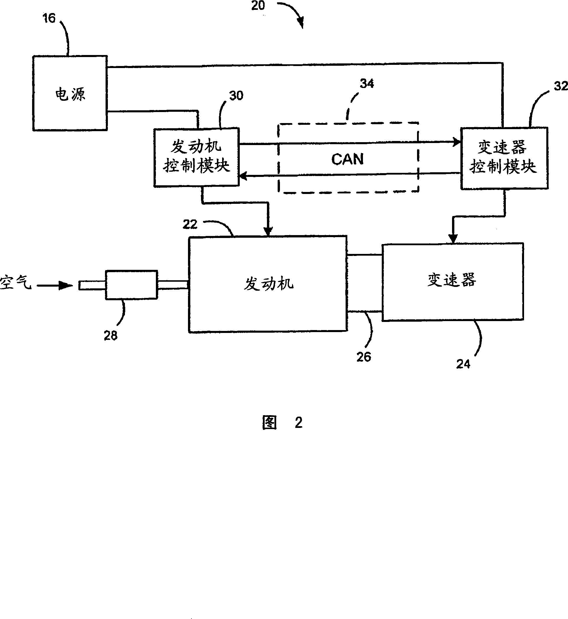
[0018] Referring now to FIG. 2 , a vehicle 20 includes an engine 22 , a transmission 24 , and a torque converter 26 . The engine 22 combusts an air and fuel mixture within cylinders (not shown) to produce drive torque. Air is drawn into the engine through a throttle valve 28 . A torque converter 26 transfers and multiplies torque from the engine 22 to the transmission 24 . Transm...


PUM


Abstract

A vehicle diagnostic system is provided. The system includes: a first control module that includes a first processor and that controls a first vehicle subsystem; and second control module that controls a second vehicle subsystem and that validates the functionality of the first processor of the first control module wherein if the second control module determines that the first processor of the first control module is faulty, the second control module shuts down the first control module.

Description

[0001] Cross References to Related Applications [0002] This application claims priority to US Provisional Application No. 60 / 841,610, filed August 31, 2006, the disclosure of which is hereby incorporated by reference. technical field [0003] The present invention relates to vehicle diagnostic systems, and more particularly to diagnostic systems for reducing operational failures of control modules. Background technique [0004] The statements in this section merely provide background information related to the present disclosure and may not constitute prior art. [0005] Referring now to FIG. 1 , one or more control modules 10 control various subsystems of the vehicle. Control module 10 typically includes a main processor 12 that includes an arithmetic logic unit (ALU) capable of computing the results of various arithmetic operations. The calculated results are used by software to control various electrical and / or mechanical components in the subsystem. [0006] Certain...

Claims


Application Information

Patent Timeline
IPC IPC(8): G05B23/02G07C5/00
CPCG05B9/02G05B23/0289G05B23/0237
Inventor W·R·梅休D·W·赖特
Owner GM GLOBAL TECH OPERATIONS LLC
Why Eureka
Try Eureka