Catalyst coated membrane, membrane electrode assembly containing the same, method of producing the same, and fuel cell including the membrane electrode assembly

A technology of membrane electrode assembly and coating membrane, which is applied in the field of catalyst coating membrane, including its membrane electrode assembly, its preparation, and fuel cells including the membrane electrode assembly, and can solve the problem of increasing the size of catalyst metal particles

Inactive Publication Date: 2008-07-16
SAMSUNG SDI CO LTD
View PDF1 Cites 18 Cited by
  • Summary
  • Abstract
  • Description
  • Claims
  • Application Information

AI Technical Summary

Problems solved by technology

Also, there is the problem that the size of the catalyst metal particles increases with the loading concentration

Method used


Image

  • Catalyst coated membrane, membrane electrode assembly containing the same, method of producing the same, and fuel cell including the membrane electrode assembly
  • Catalyst coated membrane, membrane electrode assembly containing the same, method of producing the same, and fuel cell including the membrane electrode assembly
  • Catalyst coated membrane, membrane electrode assembly containing the same, method of producing the same, and fuel cell including the membrane electrode assembly

Examples


Embodiment 1

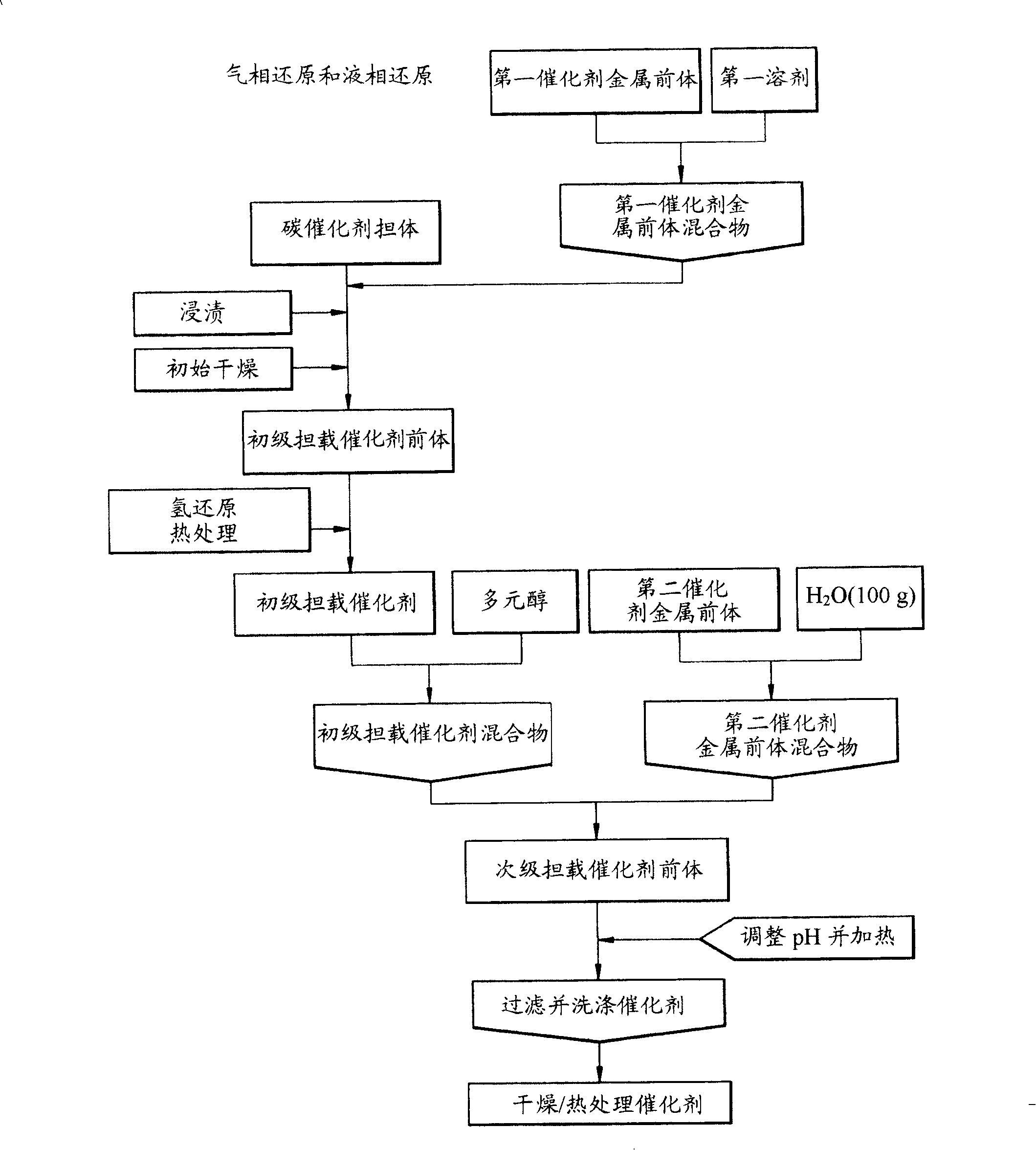
[0079] 0.89g hexachloroplatinic acid (H 2 PtCl 6 ·xH 2 O) and 0.40g ruthenium chloride (RuCl 3 ·xH 2 O) were dissolved in 2.5ml acetone, and mixed to obtain the corresponding catalyst metal precursor mixture, and then impregnated 1g of mesoporous carbon as a carbon support in a plastic bag with the catalyst metal precursor mixture. The impregnated carbon support was placed in an electric furnace and subjected to a gas phase reduction reaction in a hydrogen flow to prepare a supported catalyst (first supported catalyst) loaded with 35% by weight of PtRu.

[0080] 0.769 g of the first supported catalyst was added to 400 g of ethylene glycol to prepare a first supported catalyst mixture. Then, put 1.516g hexachloroplatinic acid (H 2 PtCl 6 ·xH 2 O) and 0.740g ruthenium chloride (RuCl 3 ·xH 2 O) Dissolved in 200 g of triple distilled water in such an amount that the final loading of catalyst metal was 70% by weight, the resulting solution was added to the first supported ...

Embodiment 2

[0084] 1.08g hexachloroplatinic acid (H 2 PtCl 6 ·xH 2O) was dissolved in 6 ml of acetone to obtain the corresponding catalyst metal precursor mixture. Then 1 g of mesoporous carbon as a carbon support was impregnated in a plastic bag with the catalyst metal precursor mixture. The impregnated carbon support was placed in an electric furnace and subjected to a gas-phase reduction reaction in a hydrogen flow to prepare a supported catalyst (first supported catalyst) loaded with 30% by weight of Pt.

[0085] 1.43 g of the first supported catalyst was added to 260 g of ethylene glycol to prepare a first supported catalyst mixture. Then, 2.692g hexachloroplatinic acid (H 2 PtCl 6 ·xH 2 O) was dissolved in 300 g of triple distilled water at levels such that the final catalyst metal loading was 60% by weight, and the resulting solution was added to the first supported catalyst mixture. The pH of the resulting mixture was adjusted to pH 11, and the mixture was then heated to 11...

Embodiment 3

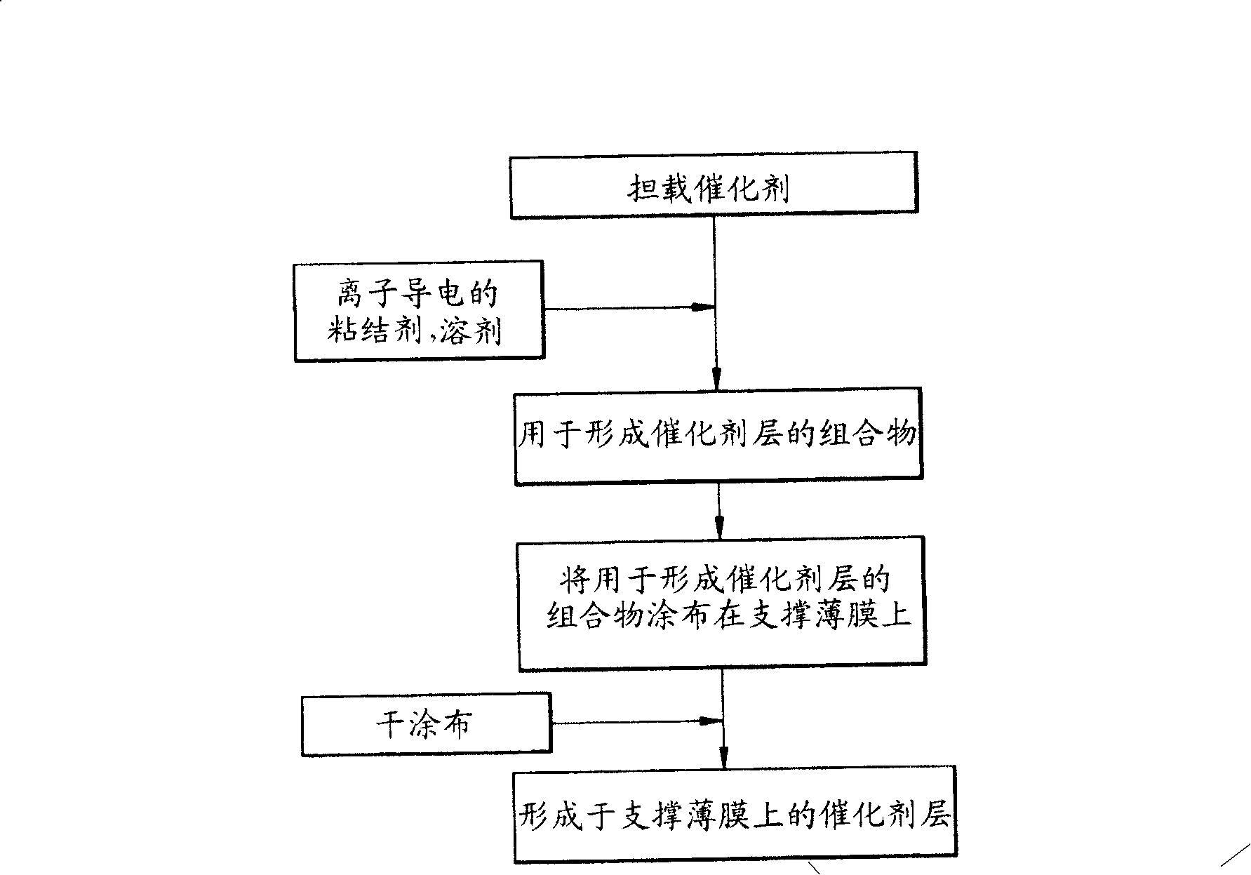
[0098] The 1.5g 70% by weight PtRu / MC supported catalyst obtained in Example 1 is mixed with 2g deionized water, 1g ethylene glycol and 2.25g 20% ​​by weight of Nafion ionomer solution to prepare a slurry for forming the catalyst layer material.

[0099] The slurry bar for forming the catalyst layer was coated on a polyethylene film with a thickness of about 30 μm, and then the coating was dried in a vacuum electric furnace at 80° C. to form a 70% weight-loaded PtRu / MC catalyst layer.

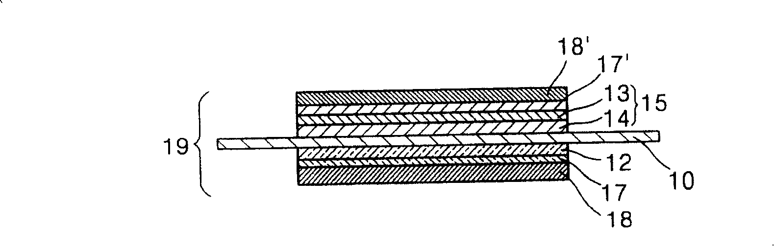
[0100] Thereafter, a PtRu black non-supported catalyst layer was formed on top of the 70% by weight supported PtRu / MC catalyst layer to constitute an anode catalyst layer. Here, the PtRu black non-supported catalyst layer was formed as follows.

[0101] A slurry for forming the catalyst layer was prepared by mixing 3 g of PtRu black with 3 g of deionized water, 2 g of ethylene glycol, and 1.875 g of a 20% by weight Nafion ionomer solution. The slurry for forming a catalyst layer was coated on...


PUM

PropertyMeasurementUnit
diameteraaaaaaaaaa
specific surface areaaaaaaaaaaa
diameteraaaaaaaaaa

Abstract

A catalyst coated membrane (CCM) comprising an anode catalyst layer having a first catalyst layer composed of a non-supported catalyst and a second catalyst layer composed of a supported catalyst, a cathode catalyst layer composed of a supported catalyst, and an electrolyte membrane interposed between the anode catalyst layer and a cathode catalyst layer, the first catalyst layer of the anode catalyst layer being disposed adjacent to the electrolyte membrane; a membrane electrode assembly (MEA) comprising the catalyst coated membrane; a method of preparing the membrane electrode assembly; and a fuel cell comprising the membrane electrode assembly, are provided. The CCM, which comprises a bilayered anode catalyst layer including the first catalyst layer composed of a non-supported catalyst and the second catalyst layer composed of a supported catalyst, exhibits reduced electrical resistance and interfacial resistance, and has increased catalyst availability. The use of the CCM and an MEA having the same results in a decrease in the interfacial resistance between the electrodes and the electrolyte membrane, a decrease in the amount of the catalyst used in the electrode catalyst layer, and a decrease in the thickness deviation in the electrode layers. The fuel cell employing the MEA exhibits maximal activity of the supported catalyst, and has improved cell characteristics such as output voltage, output density, efficiency, and the like.

Description

technical field [0001] The present invention relates to a catalyst coated membrane (CCM), a membrane electrode assembly (MEA) comprising the catalyst coated membrane, a method for preparing the catalyst coated membrane, and a fuel cell using the membrane electrode assembly, specifically, the present invention The invention relates to a novel catalyst-coated membrane, a membrane electrode assembly comprising the catalyst-coated membrane, a method for preparing the catalyst-coated membrane, and a fuel cell comprising the membrane-electrode assembly, wherein the catalyst-coated membrane employs an improved Catalytically active double-layer anode catalyst layer. Background technique [0002] Electrodes, fuels, and electrolyte membranes employed in fuel cells have been actively studied to enhance power density and output voltage by increasing energy density in fuel cells. In particular, efforts have been made to improve the catalytic activity of catalysts used in fuel cell elect...

Claims


Application Information

Patent Timeline
Patent Type & Authority Applications(China)
IPC IPC(8): H01M4/86H01M8/02H01M4/92H01M4/90B01J23/40B01J23/52B01J32/00H01M4/88H01M8/10
CPCH01M4/8828H01M4/926H01M4/8814H01M4/8882H01M4/8668H01M4/8657Y02E60/50H01M4/921H01M4/8875H01M4/928H01M4/881H01M4/86H01M4/88
Inventor 朴灿镐李雪娥张赫金之来刘大钟朱相熏
Owner SAMSUNG SDI CO LTD
Why Eureka
Try Eureka