Vehicle brake system having a pump

A vehicle braking and front chamber technology, applied in the direction of brakes, etc., can solve the problems of loud noise, pressure flow brake pedal failure, etc., and achieve the effect of preventing the generation of noise

Inactive Publication Date: 2008-07-30
ROBERT BOSCH GMBH
View PDF0 Cites 0 Cited by
  • Summary
  • Abstract
  • Description
  • Claims
  • Application Information

AI Technical Summary

Problems solved by technology

This filling can lead to undesirably loud noises, shocks inside the pressure flow and / or failure of the associated brake pedal

Method used


Image

  • Vehicle brake system having a pump
  • Vehicle brake system having a pump

Examples


Embodiment Construction

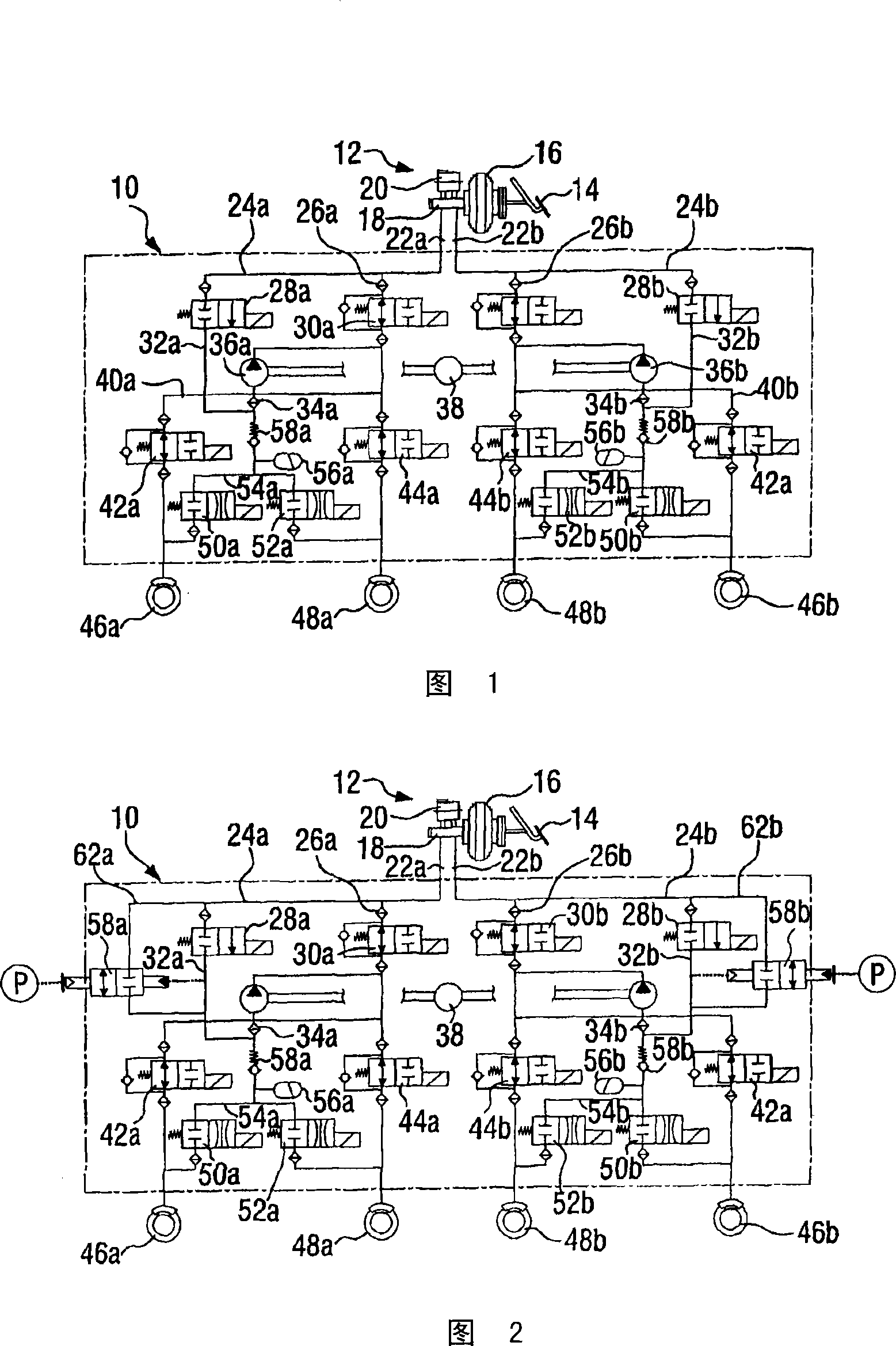
[0017] FIG. 1 shows a hydraulic circuit diagram of a vehicle brake system 10 according to the prior art. The vehicle brake system 10 includes a brake actuating unit 12 , which conventionally includes a brake pedal 14 , a brake booster 16 , a master brake cylinder 18 and a brake fluid container 20 .

[0018] Two lines 22 a and 22 b are connected to master brake cylinder 18 and to brake fluid container 20 arranged thereon, which each belong to two separate brake circuits. The two brake circuits are designed substantially identically and are distinguished below by using the reference symbols "a" and "b". For the sake of simplification, the ensuing description is limited to the first of the two brake circuits, the other brake circuit extending from it, as already mentioned, having substantially the same construction.

[0019] The line 22a splits into two lines 24a and 26a, to which a high-pressure distribution valve 28a or a low-pressure distribution valve 30a is connected. The ...


PUM


Abstract

Disclosed is a vehicle brake system having a pump and a prechamber, from which the pump can extract a fluid by suction, and having a switching valve, by means of which fluid can optionally be fed to the prechamber. A bypass valve connected in parallel with the switching valve is switched as a function of the pressure difference between the ambient pressure and the prechamber pressure.

Description

technical field [0001] The present invention relates to a vehicle braking device with a pump and a front chamber and a valve, wherein the pump can suck fluid from the front chamber, and the front chamber can selectively supply fluid by means of the valve. Background technique [0002] Various systems are known from the field of vehicle brake systems in which a pump is provided for efficiently reducing or building up the brake pressure. The pump sucks the brake fluid out of the front chamber and then selectively returns it to the reservoir in order to reduce the brake pressure (anti-lock operation of the vehicle brakes) or pumps the hydraulic fluid in the direction of the vehicle brakes ( e.g. within the framework of the Electronic Stability Program). [0003] Inside the hydraulic line in which the pump with its antechamber is connected, valves are also provided for this purpose, by means of which the antechamber can be selectively supplied with fluid. When the valve is clo...

Claims


Application Information

Patent Timeline
Patent Type & Authority Applications(China)
IPC IPC(8): B60T8/48
CPCB60T8/4872
Inventor C·博德曼
Owner ROBERT BOSCH GMBH
Why Eureka
Try Eureka