
Device for controlling the connection to be displaced temporary of two unit which can be pressurized with pressure medium with pressure medium source

A pressure medium and unit technology, applied in the direction of mechanical equipment, non-mechanical actuated valves, engine components, etc., can solve problems such as insufficient safety, reliability, and poor quality, and achieve the effect of simple design

Active Publication Date: 2007-09-12
MAN DIESEL GERMANY BRANCH OFFICE OF MAN DIESEL SE
View PDF1 Cites 0 Cited by
  • Summary
  • Abstract
  • Description
  • Claims
  • Application Information

AI Technical Summary

Problems solved by technology

This result can be particularly bad when a device of the type described here is used to control the fuel injection of two different cylinders
In this regard these known devices have proven to be insufficiently safe and reliable

Method used


Image

  • Device for controlling the connection to be displaced temporary of two unit which can be pressurized with pressure medium with pressure medium source
  • Device for controlling the connection to be displaced temporary of two unit which can be pressurized with pressure medium with pressure medium source
  • Device for controlling the connection to be displaced temporary of two unit which can be pressurized with pressure medium with pressure medium source

Examples


Embodiment Construction

[0022] The main application field of the present invention is, for example, a two-stroke large diesel engine that can be used as a marine engine. In this regard, it involves engines with lower speeds and larger piston strokes. This type of engine usually includes multiple cylinders arranged in rows. The basic structure and working methods of such engines are known.

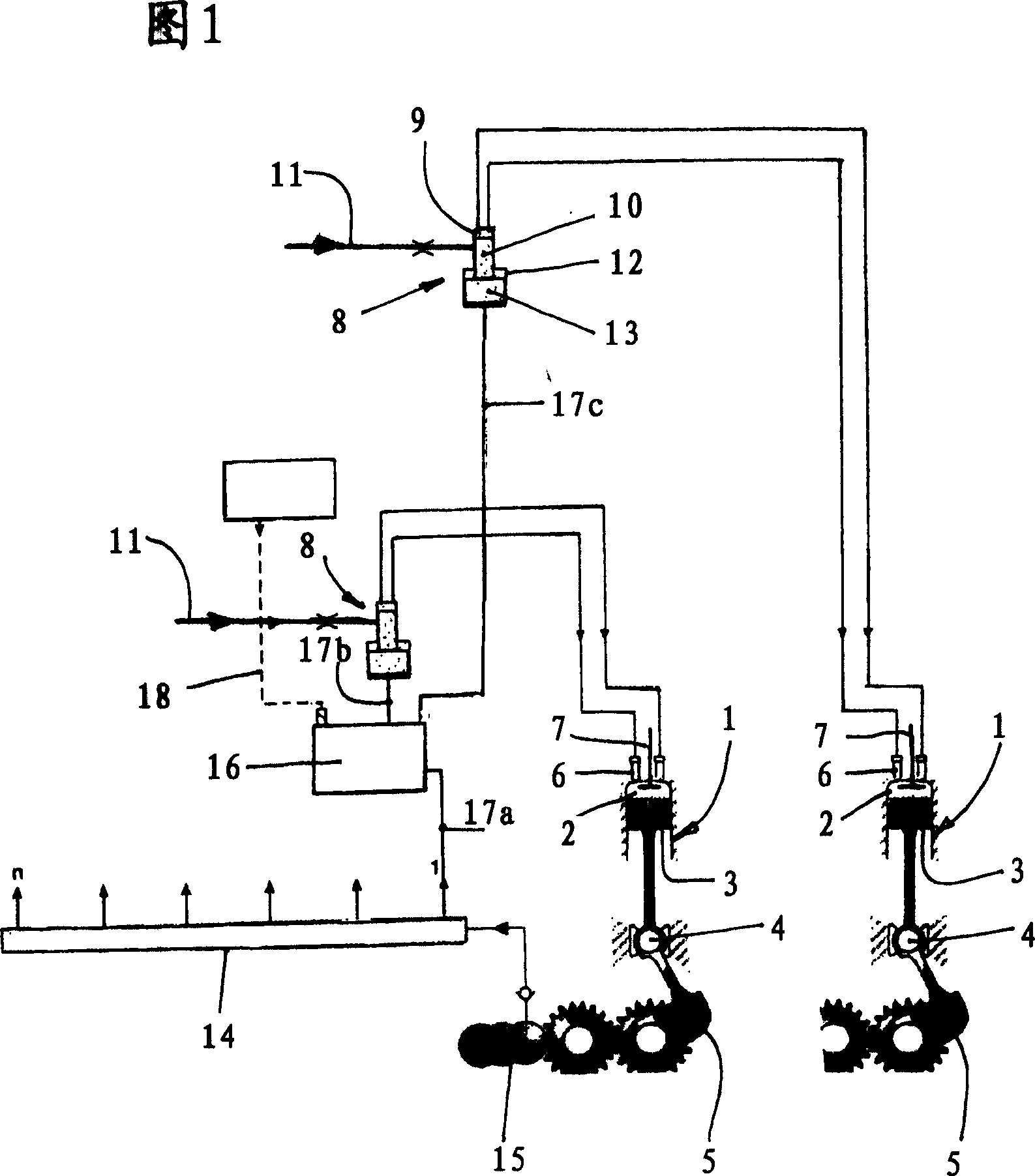
[0023] Figure 1 schematically shows two cylinders 1. Each cylinder 1 has a combustion chamber 2 bounded by a piston 3 that moves up and down, where the piston interacts with a crankshaft 5 via a crosshead 4. The combustion chamber 2 is charged with air through an intake port not shown in detail here, which is arranged in the cylinder liner and controlled by the piston 3 moving up and down, and is charged with fuel through a fuel injection valve 6 arranged in the area of ​​the cylinder head. Each cylinder is provided with two fuel injection valves 6 in the example shown in the figure. The exhaust gas generated during c...


PUM


Abstract

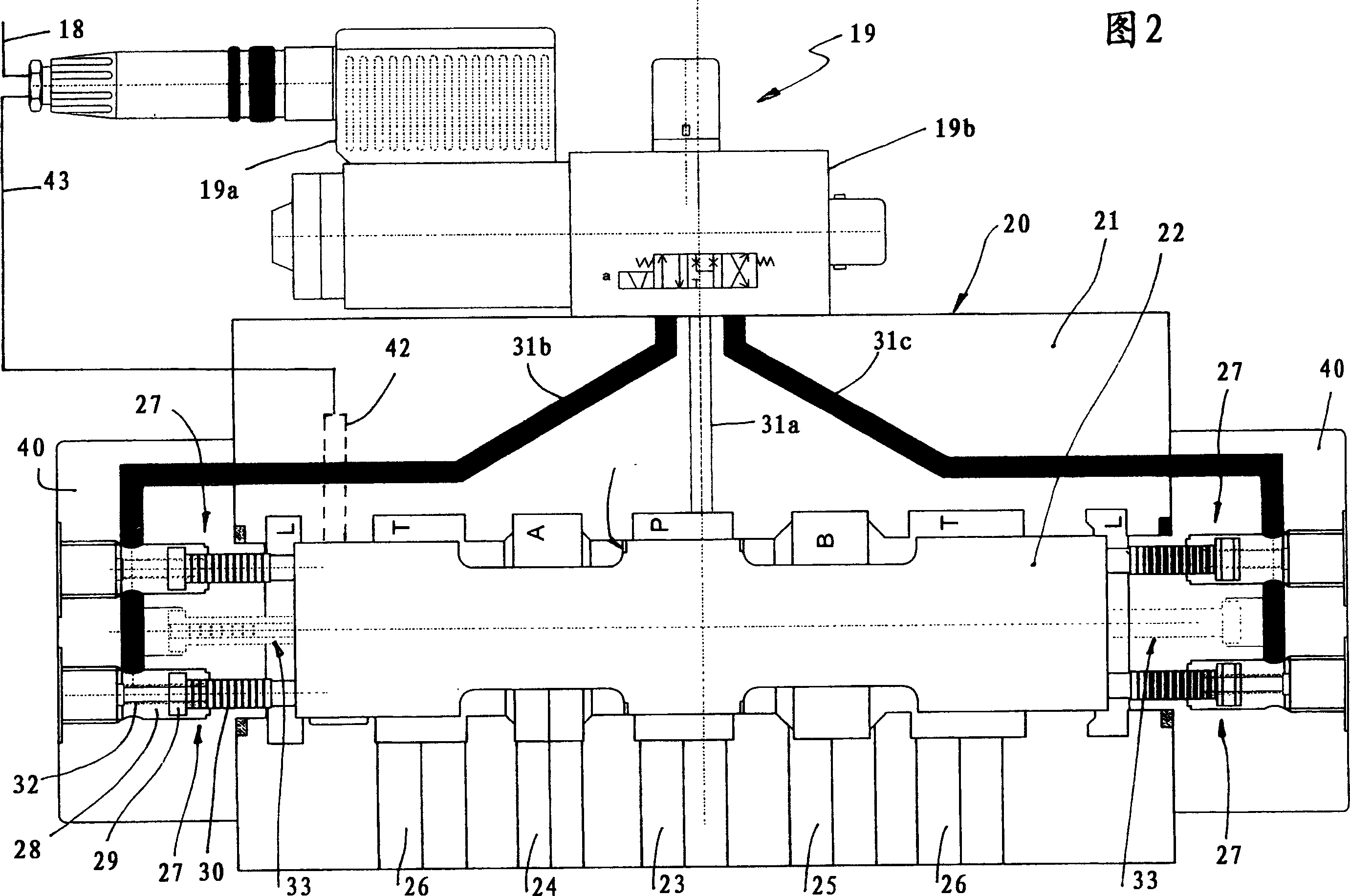
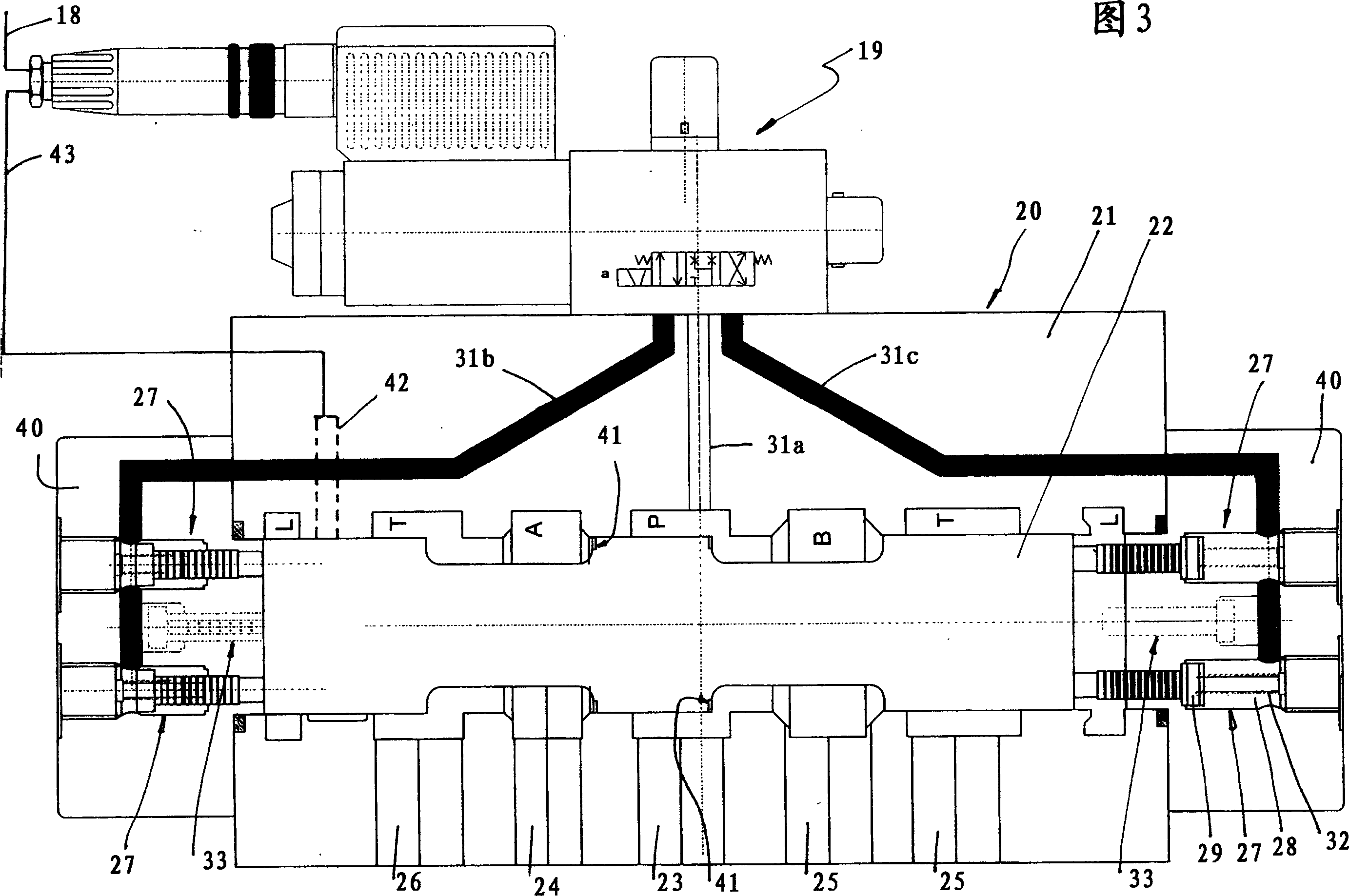
This device is a valve mechanism for connecting a pressure medium source to a machine for giving a shock, and has the valve mechanism having a valve 19 and a main control valve 20 started by an engine signal. A casing for storing a slider 22 cooperating with an operation device has an inlet 23 connected to the medium source and outlets 24 and 25 corresponding to the machine. The outlets can be connected to the inlet when the slider exists in the center, and is released from a load, and can be alternately connected to the inlet(23) when the slider is dislocated from the center. The operation device corresponding to the slider has a device for moving the slider from the center. The device is started when the valve 19 is started, and is stopped when there is no engine signal. The operation device has the device and a centering device of an always operation state. The device overcomes the device . When stopping the device , the slider is placed in the center by the device .

Description

Technical field [0001] The invention relates to a device for controlling the time-staggered connection of two pressure medium-loaded units and a pressure medium source, in particular for activating engines, especially two-stroke large diesel engines, which are time-staggered Two hydraulically controllable injection devices, preferably assigned to different cylinders, have a control valve device that establishes a connection between the pressure medium source and the unit to be loaded. The control valve device includes a pilot controllable by an engine signal. The control valve and a cooperating main control valve designed as a spool valve. The main control valve housing a movable main valve core cooperating with an associated operating device has a housing connected to a pressure medium source When the main spool is in its middle position, these outlets are isolated from the inlet and unloaded and can be alternately connected to the inlet through the corresponding offset of the ma...

Claims


Application Information

Patent Timeline
IPC IPC(8): F01L9/02F02M47/00F02M57/04F01L9/10
CPCF01L9/02F02M59/105F01L9/10F01L1/34
Inventor P·森克
Owner MAN DIESEL GERMANY BRANCH OFFICE OF MAN DIESEL SE
Learn More