
Fluid machinery with high pressure and lower pressure sectors

A technology of fluid machinery and fluid medium, applied in mechanical equipment, liquid fuel engines, components of pumping devices for elastic fluids, etc., can solve the distortion and deformation of the outer shell, uneven heating of the outer shell, and scraping of the outer shell by blades, etc. problems, to achieve the effect of small mass, saving materials and time, improving starting characteristics and running characteristics

Inactive Publication Date: 2003-08-20
SIEMENS AG
View PDF0 Cites 8 Cited by
  • Summary
  • Abstract
  • Description
  • Claims
  • Application Information

AI Technical Summary

Problems solved by technology

In this case, the conduction of the steam into the blade region by means of a sealing shell results in uneven heating of the outer casing along its circumference
This causes thermal stress and thermal deformation, i.e. warping of the casing, which in turn can cause the blades to graze the casing

Method used


Image

  • Fluid machinery with high pressure and lower pressure sectors
  • Fluid machinery with high pressure and lower pressure sectors
  • Fluid machinery with high pressure and lower pressure sectors

Examples


Embodiment Construction

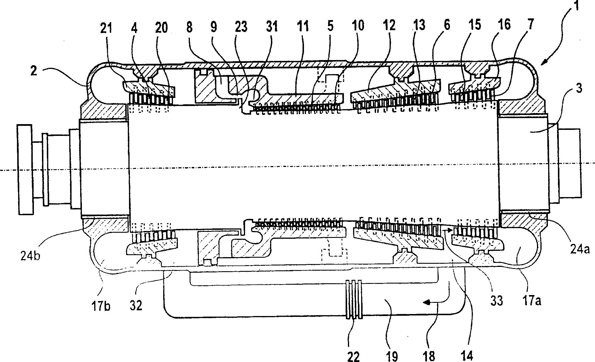
[0023] figure 1 It is a simplified longitudinal sectional view of a fluid machine 1 . The fluid machine has an outer casing 2 , several inner casings 11 , 12 , 16 , 21 and a rotor 3 . Four blade regions 4 , 5 , 6 , 7 are provided on the rotor 3 . These four blade areas are divided in the present embodiment into two inner blade areas 5 , 6 and two outer blade areas 4 , 7 . The two outer blade regions 4 , 7 are arranged opposite each other and point away from the inner blade region 5 , 6 respectively. An inlet opening 8 is contained in the outer casing upstream of the first inner vane region 5 . A control stage 9 is arranged starting from the inlet opening 8 towards the first inner vane region 5 . After the adjustment stage 9 there is also an expansion section 31 towards the first inner blade region 5 . In the illustrated embodiment, guide vanes 10 are arranged on the inner housing 11 in the first inner vane region 5 . Following the first inner blade region 5 is a further ...


PUM


Abstract

A fluid-flow machine includes an outer casing having a rotationally mounted rotor with three blade regions. The blade regions are divided into an inner blade region and two outer blade regions, the two outer blade regions pointing outward toward the outer casing end. The fluid-flow machine includes one or more outlet openings, via which the flow medium is divided into two partial flows. The two partial flows then flow through the respective outer blade regions. The invention also relates to a method of operating a steam turbine.

Description

technical field [0001] The invention relates to a fluid machine having a housing on which a rotor is rotatably mounted with three blade regions which communicate with each other from a fluid flow point of view. The invention also relates to a method for operating such a fluid machine as a steam turbine. Background technique [0002] Known fluid machines have a high-pressure steam section and a low-pressure steam section, which can be of single-shell or double-shell construction. Such a fluid machine, in particular a steam turbine, is described in German Patent Application 1997P03012 DE. Since the double-shell structure does not belong to the technical field of the present invention, it will not be further described. This monocoque structure consists of a rotor with two single-channel blade regions, which are each directed towards the corresponding housing end. One of the blade areas is used as a high-pressure steam blade area, and the other blade area is used as a low-pre...

Claims


Application Information

Patent Timeline
Patent Type & Authority Applications(China)
IPC IPC(8): F01D25/00F01D1/02F01D1/04F01D25/16F01D25/24F01D25/26F04D27/00F04D29/10F04D29/32
CPCF01D1/023F01D1/04
Inventor 格哈德·克劳斯英戈·斯蒂芬
Owner SIEMENS AG
Learn More