Roll stand

A technology of rolling mill stand and rolling direction, applied in the direction of guide/positioning/alignment device, etc., can solve problems such as damage and damage of the guide surface, and achieve the effect of reducing the degree of damage, avoiding downtime, and reducing repair costs

Active Publication Date: 2009-09-23
SMS DEMAG AG
View PDF2 Cites 3 Cited by
  • Summary
  • Abstract
  • Description
  • Claims
  • Application Information

AI Technical Summary

Problems solved by technology

Huge damage can then be caused as the impact force is transmitted from the input or output guides to the mill stand
In particular, the guide surfaces for the input or output guides on the rolling mill stand or on the corresponding surrounding components can be damaged as a result.

Method used


Image

  • Roll stand
  • Roll stand
  • Roll stand

Examples


Embodiment Construction

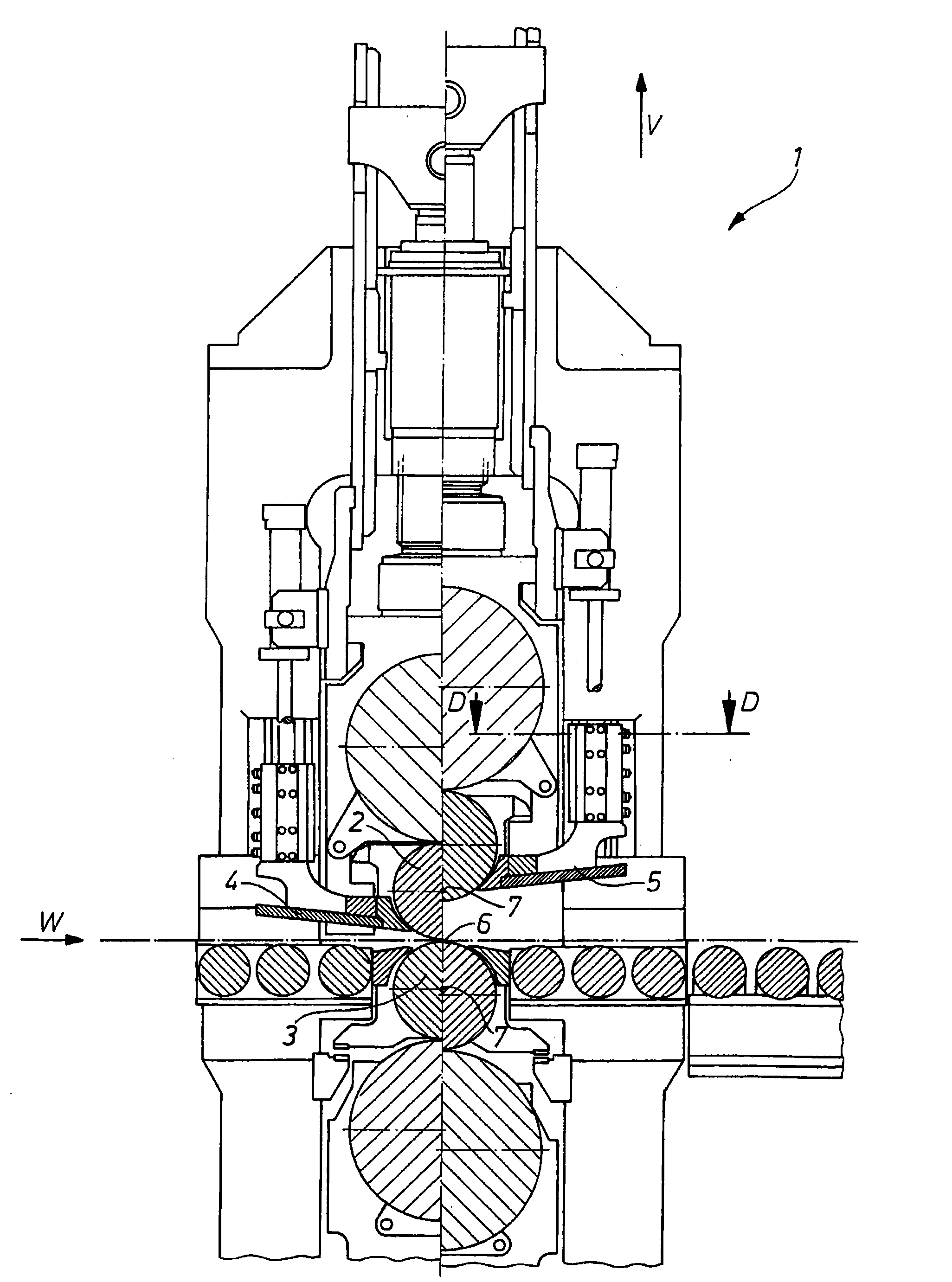
[0020] exist figure 1 shows a rolling stand 1 of a rolling installation, which is constructed in a generally known manner. On both sides of the center plane, the (working) rolls 2 , 3 of the rolling stand are shown in different vertical positions, that is to say with different roll gaps 6 between the rolls 2 , 3 . The axes 7 of the rollers 2 , 3 are here perpendicular to the plane of the drawing. The input guide 4 and the output guide 5 are located in the rolling direction W in front of and behind the rolls 2 , 3 in a known manner. The two guides 4 , 5 are adjustable in the vertical direction V.

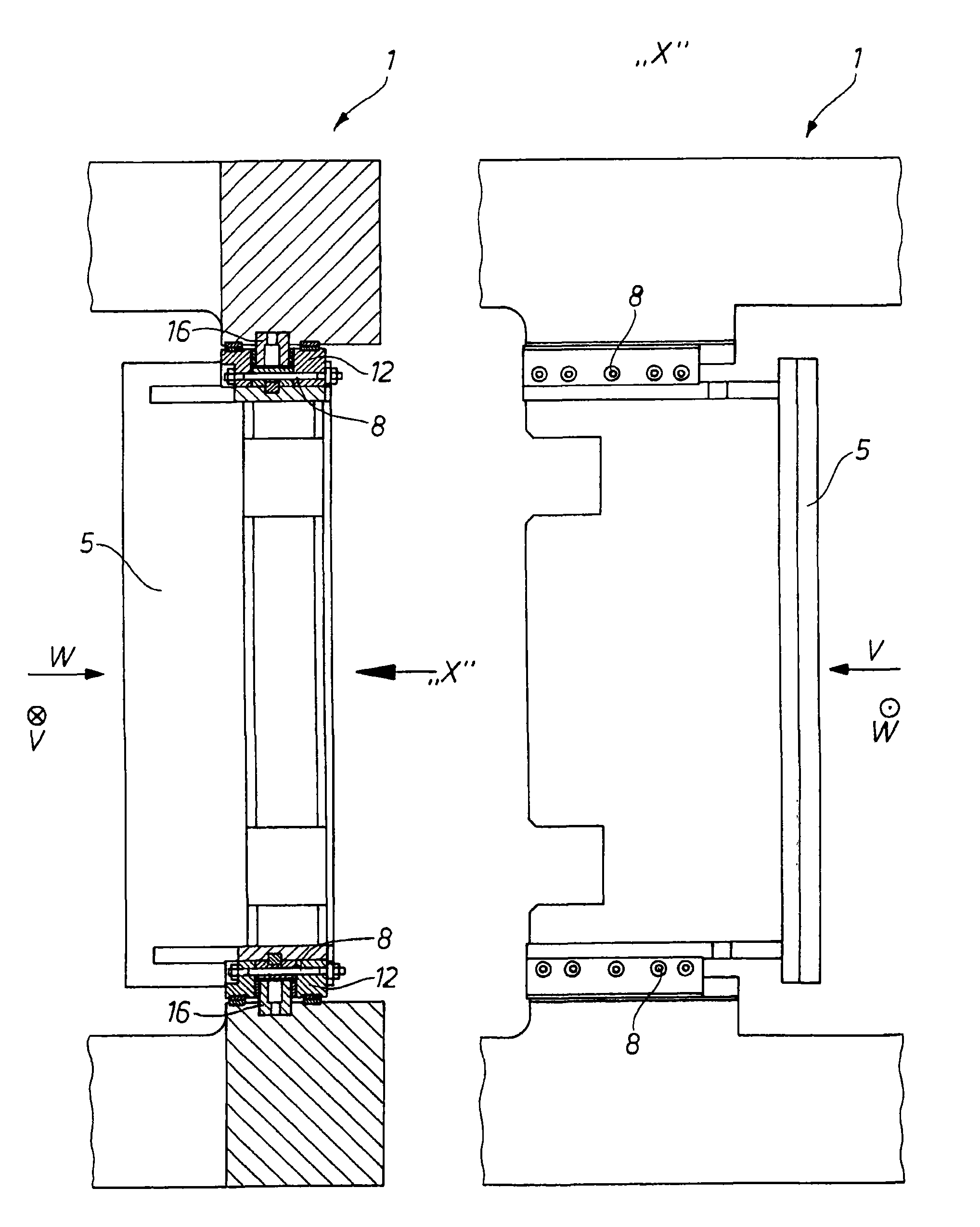
[0021] exist figure 2 shown in the figure 1 The section D-D in the and figure 1 Compatible top view. Here again the output guides 4 , 5 are shown together with their lateral guides, so that the output guides can be adjusted in the vertical direction V or can be moved.

[0022] Support elements 16 , which are designed as elongated rods extending in the vertical direction V, ar...


PUM


Abstract

The invention relates to a roll stand (1) with a number of rollers (2, 3) and with an incoming guide (4) and / or an outgoing guide (5) which is / are fixed on the roll stand (1) before or after the rolling gap (6) in the rolling direction (W), respectively, and which is / are adjustably arranged in the direction perpendicular to the axis (7) of the rollers (2, 3) and perpendicular to the rolling direction (W), particularly in the vertical direction (V). To minimize damage in case of an accident, the invention provides for a predetermined breaking point (9) in the fixing means (8) which fixes the incoming guide (4) and / or the outgoing guide (5) on the roll stand (1).

Description

technical field [0001] The invention relates to a rolling mill stand with a plurality of rolls and having an input guide and / or an output guide which are fixed to the rolling mill before or after a roll gap in the rolling direction On the stand, and along the direction perpendicular to the axis of the roll and perpendicular to the rolling direction, especially along the vertical direction can be adjusted. Background technique [0002] Rolling mill stands of this type are known. DE 101 16 988 A1 discloses a rolling mill stand with means for raising or lowering the intermediate roll stand or the work roll stand when changing rolls. The roller stand is arranged on the guide member, and the roller stand can run vertically along the guide member. A similar solution is known from DE 1 940 414 A1. [0003] The input guide and the output guide provided on the stand of the rolling mill must receive working stress along the horizontal direction, and the input guide and the output g...

Claims


Application Information

Patent Timeline
Patent Type & Authority Applications(China)
IPC IPC(8): B21B39/16
CPCB21B39/16B21B39/165
Inventor M·博兰J·舒尔梅斯特M·瓦格纳
Owner SMS DEMAG AG
Why Eureka
Try Eureka