Hardware timer based time-delay method

A timer and hardware technology, applied in the direction of instruments, calculations, electrical digital data processing, etc., can solve the problems of inaccurate time delay, etc., and achieve the effect of accurate time delay and strong versatility

Inactive Publication Date: 2008-08-06
HUANDA COMPUTER (SHANGHAI) CO LTD
View PDF0 Cites 13 Cited by
  • Summary
  • Abstract
  • Description
  • Claims
  • Application Information

AI Technical Summary

Problems solved by technology

[0006] In view of the above problems, the present invention provides a delay method based on a hardware timer, which uses a combination of software and hardware to overcome the defect that the pure software method cannot accurately delay the time

Method used


Image

  • Hardware timer based time-delay method
  • Hardware timer based time-delay method
  • Hardware timer based time-delay method

Examples


Embodiment Construction

[0027] In order to have a further understanding of the working process of the present invention, it will be described in detail below in conjunction with the accompanying drawings.

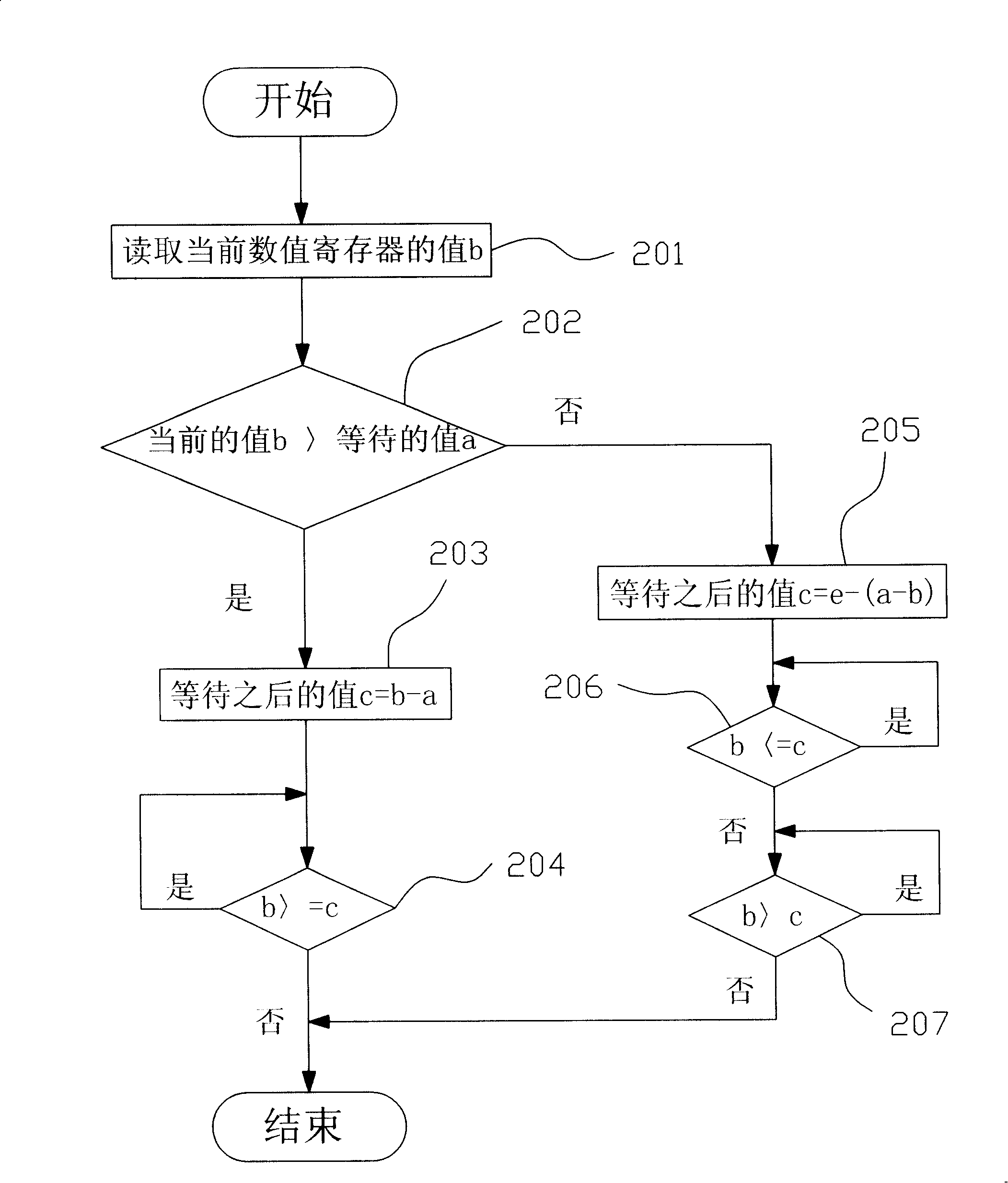
[0028] see figure 2 Shown is the flow chart of the first embodiment of the delay method based on the hardware timer provided by the present invention; in this embodiment, the hardware timer is a watchdog timer (Watchdog timer) , the timer can start decrementing at a constant speed from a pre-set maximum count value, and the timer value is decremented by 1 every time it decrements, and when it is reduced to 0, it returns to the maximum value cycle counting again.

[0029] Such as figure 2 As shown, the delay method includes the following steps: the program reads the current value b (step 201) of the numerical register in the hardware timer; the program compares the current value b of the numerical register with the time a that needs to wait, and if b is greater than a, then execute Step 203, ot...


PUM


Abstract

The present invention relates to a time delay method based on a hardware timer. The method combines the hardware timer with a program stored in a computer to realize time delay, and the timer is a numerical decreasing type timer or a numerical increasing type timer. The time delay method reads a current timer value through the program and judges whether the current timer value reaches latency time so as to achieve the objective of time delay. The time delay method adopts the mode of combining software control with hardware timing, depends on the accuracy of timing and the flexibility of software control to realize accurate time delay. Moreover, when the hardware or software environment changes, the time delay precision of the time delay method cannot be affected too much, thereby the time delay method has high adaptability.

Description

【Technical field】 [0001] The invention relates to a time delay method, in particular to a time delay method based on a hardware timer. 【Background technique】 [0002] In the development process of the operating system driver software, it is often necessary to operate the hardware registers, such as setting the GPIO port of the CPU, etc., and the operation of the hardware by the driver software often requires the hardware to execute operation instructions at a specified time, so in the software In development, a delay program needs to be set to ensure that the hardware can respond to the operating instructions of the software in a correct and timely manner. [0003] Most of the current delay methods are completed by a delay function, such as figure 1 As shown, in this delay function, the program achieves the purpose of delay by executing a number of loop statements, including the following steps: first, the program judges whether the preset number of cycles d has been reache...

Claims


Application Information

Patent Timeline
Patent Type & Authority Applications(China)
IPC IPC(8): G06F11/00G06F9/44
Inventor 杨春妮臧东明王怀井
Owner HUANDA COMPUTER (SHANGHAI) CO LTD
Why Eureka
Try Eureka