Permanent magnetic gravitation inertia conversion engine

A technology of engines and permanent magnet rotors, applied in generators/motors, electrical components, etc., can solve problems such as inability to continuously generate energy, depletion of petroleum resources, and pollution emissions

Inactive Publication Date: 2008-08-06
刘增民 +1
View PDF0 Cites 6 Cited by
  • Summary
  • Abstract
  • Description
  • Claims
  • Application Information

AI Technical Summary

Problems solved by technology

[0006] The disadvantage of traditional engines is that oil resources are facing depletion, and they emit pollution, which is not conducive to environmental protection
The disadvantage of permanent magnet motor and permanent magnet generator in the use of permanent magnet materials is that permanent magnets only play the role of transmission and energy

Method used


Image

  • Permanent magnetic gravitation inertia conversion engine
  • Permanent magnetic gravitation inertia conversion engine
  • Permanent magnetic gravitation inertia conversion engine

Examples


Embodiment Construction

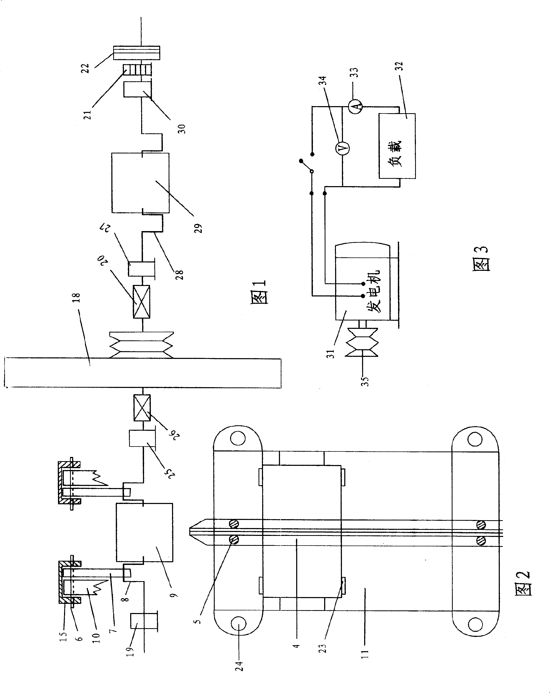
[0081] The basic working principle of the present invention will be further described in detail below in conjunction with the drawings and the present embodiment: What is described in claim 1 is a rotor crankshaft mechanism with symmetrical crankshaft directions of 180 degrees each other, with an inertia wheel in the middle. , They are fixedly connected together by a coupling. Four connecting wheels are supported by two shafts, and two permanent magnet chains are installed on the sprocket to cooperate with the rotor crankshaft system. The magnetic pole direction of the permanent magnet rotor is parallel to the two circular planes of the cylindrical rotor. Picture 9

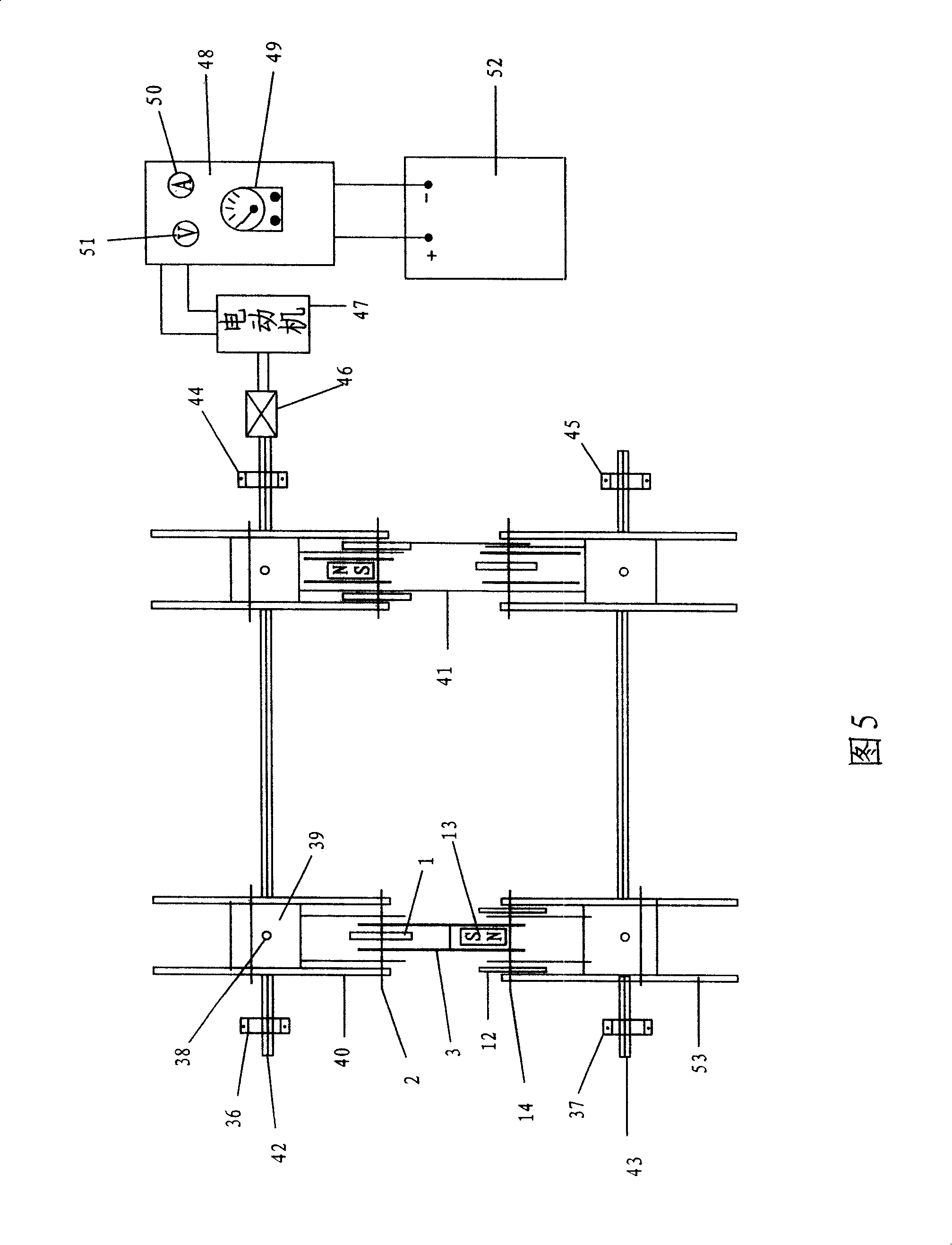
[0082] The direction of the poles of the rectangular magnets on the flux linkage cart is straight and long. Picture 10

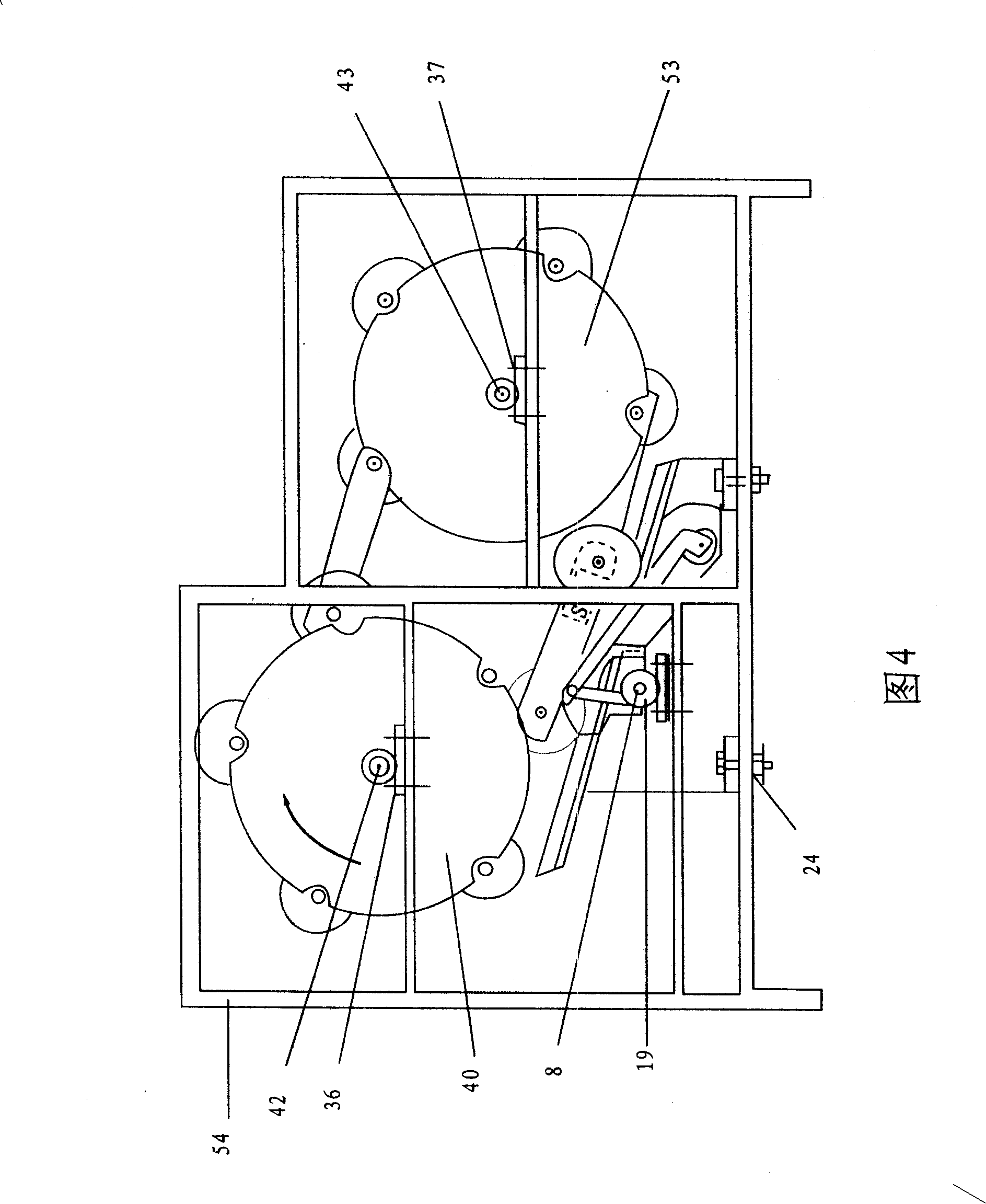
[0083] The crankshaft connecting rod, the slider, the movable track and the permanent magnet link change the force direction of the permanent magnet on the magnet link car, making it consistent wi...


PUM


Abstract

The invention provides a permanent magnetic attraction inertia conversion engine. The invention relates to a novel engine, in particular to an engine which mainly adopts the attraction force interreaction of a PM rotor and a PM on a PM chain to produce the power. As the attraction force directions of the PM rotor and the PM on the PM chain are opposite, the forced direction of the PM chain corresponding to the PM rotor should be reversed to ensure that the rotation directions of the PM chain and the PM rotor are identical. The felling direction process of the PM chain is as follows: the magnetic body of the PM chain passes the downward force to a rear wheel of a magnetic chain vehicle, the rear wheel passes the force to a movable track which passes to a sliding block and a connecting rod through an upper shaft, the connecting rod is used to press toward an angle crank, as the angle crank is in the direction of left at the time, the direction of the passed-down press and the forced direction of the PM rotor are consistent, the two kinds of forces act together to actuate the PM rotor to rotate widdershins; as the angle crank PM rotor and an inertia wheel are axially and fixedly connected with each other, the inertia wheel also generates the anticlockwise rotational moment.

Description

Technical field [0001] The invention relates to a new type of engine, more specifically: it is an engine that uses the gravitational interaction between a permanent magnet rotor and a permanent magnet on a permanent magnet chain to generate power. Background technique [0002] Traditional engines use petroleum to ignite and expand in cylinders to generate pressure, and pistons drive connecting rods, crankshafts, and inertia wheels to rotate. There is no unfueled engine. [0003] The traditional use of permanent magnet materials only plays a role in transmission, such as permanent magnet motors. Its basic principle is to use electric energy to generate a rotating magnetic field in the stator, and the gravitational force of the rotating magnetic field drives the permanent magnet rotor of the motor to rotate. In fact, it turns electrical energy into mechanical energy. For example, the so-called permanent magnet generator uses other power to drive the permanent magnet rotor to rotate...

Claims


Application Information

Patent Timeline
IPC IPC(8): H02N11/00
Inventor 刘增民刘斌
Owner 刘增民
Why Eureka
Try Eureka