Liquid crystal display device and electronic apparatus including the same

A liquid crystal display device, liquid crystal technology, applied in static indicators, nonlinear optics, optics, etc., can solve problems such as low visibility, and achieve the effect of suppressing deterioration

Inactive Publication Date: 2008-08-13
SONY CORP
View PDF6 Cites 2 Cited by
  • Summary
  • Abstract
  • Description
  • Claims
  • Application Information

AI Technical Summary

Problems solved by technology

However, reflective liquid crystal display devices involve the problem that visibility is extremely poor when ambient light is dark

Method used


Image

  • Liquid crystal display device and electronic apparatus including the same
  • Liquid crystal display device and electronic apparatus including the same
  • Liquid crystal display device and electronic apparatus including the same

Examples


no. 1 example

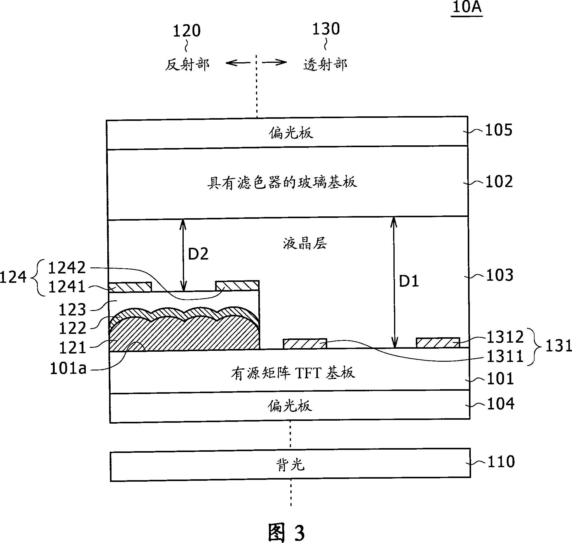
[0075] 3 is a cross-sectional view of a reflective and transmissive combined use type liquid crystal display device according to a first embodiment of the present invention.

[0076] The liquid crystal display device 10A according to the first embodiment of the present invention basically includes a first transparent substrate 101, a second transparent substrate 102, a liquid crystal layer 103, a first polarizer 104, a second polarizer 105, and a backlight 110 as main constituent elements.

[0077] In the liquid crystal display device 10A of the first embodiment, a liquid crystal layer 103 including a plurality of liquid crystal molecules is basically provided between the first transparent substrate 101 and the second transparent substrate 102 . In other words, the liquid crystal layer 103 is interposed between the first transparent substrate 101 and the second transparent substrate 102 .

[0078] In the liquid crystal display device 10A, the reflective portion 120 and the tra...

no. 2 example

[0123] 8 is a cross-sectional view of a reflective and transmissive combined use type liquid crystal display device according to a second embodiment of the present invention.

[0124] 9A and FIG. 9B are schematic diagrams showing the state of voltages and liquid crystals in the black display phase when the first method is used and the state of the white display phase when the first method is used in the second embodiment of the present invention, respectively. View of the voltage and state of the LCD.

[0125] The second embodiment of the present invention shows a structural example when using the second switching system.

[0126] In the liquid crystal display device 10B of the second embodiment, the liquid crystal layer 103 containing a plurality of liquid crystal molecules is substantially sandwiched between the first transparent substrate 101B and the second transparent substrate 102B. In other words, the liquid crystal layer 103 is sandwiched between the first transparent...


PUM


Abstract

The present invention provides a liquid crystal display device in which a direction of an orientation axis of a liquid crystal is changed based on an electric field component in a direction different from a normal direction of a main surface of a substrate, and electronic equipment including the liquid crystal display device. , the liquid crystal display device includes: a transmissive part and a reflective part arranged on the substrate; wherein, the voltage applied to the liquid crystal in the transmissive part is different from the voltage applied to the liquid crystal in the reflective part. The liquid crystal display device of the present invention can be mass-produced with high yield, and can suppress image quality deterioration.

Description

[0001] Cross References to Related Applications [0002] The present invention contains subject matter related to Japanese Patent Application JP 2007-026852 filed in the Japan Patent Office on Feb. 6, 2007, the entire content of which is hereby incorporated by reference. technical field [0003] The present invention relates to a liquid crystal display device using a combination of reflective display and transmissive display, and electronic equipment including the liquid crystal display device. Background technique [0004] Liquid crystal display devices are widely used as display devices for various electronic devices by taking advantage of the characteristics of each liquid crystal display device being slim and consuming less power. [0005] For example, various electronic equipment using liquid crystal display devices are known, such as notebook personal computers, display devices for car navigation, personal digital assistants (PDAs), mobile phones, digital cameras, and ...

Claims


Application Information

Patent Timeline
Patent Type & Authority Applications(China)
IPC IPC(8): G02F1/133G02F1/1362G02F1/1335G02F1/13363G02F1/1343
CPCG02F1/133555G02F1/134363G09G3/3611G09G2300/0426G09G2300/0456G02F1/134345G02F1/133G02F1/1335
Inventor 山口英将田中大直野口幸治
Owner SONY CORP
Why Eureka
Try Eureka