Failure protection discharge valve for pressure vessel

A technology for containers and control valves, applied to pressure vessels, equipment for discharging from pressure vessels, methods for container discharge, etc., which can solve problems such as reducing working pressure

Inactive Publication Date: 2010-05-26
PRAXAIR TECH INC
View PDF15 Cites 0 Cited by
  • Summary
  • Abstract
  • Description
  • Claims
  • Application Information

AI Technical Summary

Problems solved by technology

Most mass flow controllers are estimated to reduce the working pressure by 20kPa (150 Torr)

Method used


Image

  • Failure protection discharge valve for pressure vessel
  • Failure protection discharge valve for pressure vessel
  • Failure protection discharge valve for pressure vessel

Examples


Embodiment Construction

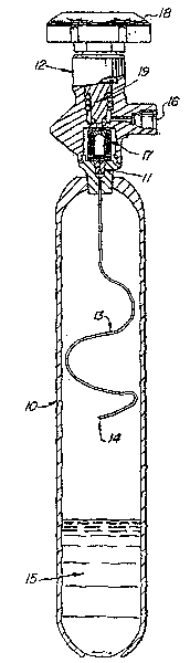
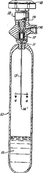
[0029] See attached figure 1 , the present invention looks like a typical delivery device from the outside, and it includes a capacity 500cc gas cylinder 10 with a cylinder overhead valve 12 at the top, and has an outlet 16. The interior or cylinder contains a capillary tube 13 with an inlet 14 which supplies arsine gas to the valve inlet 11. The liquid arsine reservoir 15 located at the bottom of the cylinder 10 will replenish the arsine gas as soon as it leaves the cylinder and maintain the vapor pressure within the cylinder until depleted. Regulator 17 located within valve 12 contains a bellows assembly 28 which automatically controls the discharge of arsine gas from the cylinder. The handle 18 enables manual control of the main valve element 19 .

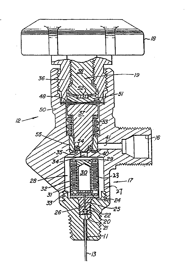
[0030] figure 2 The internal structure of the regulator 17 and the overhead valve 12 is shown in detail. Along the pipeline of the arsine gas exiting the overhead valve 12, the gas first enters the valve inlet 11 through th...


PUM


Abstract

The invention applies a pressure response valve so as to provide an effective invalid safety system, thus being used for preventing the risky drainage of a fluid in a pressure gas cylinder or a gas tank. The gas can be prevented from being exhausted out of the gas tank by the motion of a diaphragm control valve till that a prearranged pressure condition appears at the downstream of a check valve.The system is especially favourable for the delivery of arsine gas and provides a plurality of safety protection for accidental exhaust.

Description

[0001] The present invention is a divisional application with the Chinese invention patent application number 03138413.7, the title of the invention being "failure protection exhaust valve for pressure vessels", and the filing date being August 10, 1999. technical field [0002] The present invention relates to a vent valve for a storage container like a pressure container or a gas cylinder provided with multiple protections against accidental leakage of the contents of the container. Background technique [0003] Many industrial processes and production practices require the use of highly toxic fluids. The production of semiconductor materials is an example of such an implementation where safe storage and containment of highly toxic hydrogen-containing or halogen-containing gases is essential. Such gases include silane, germane, ammonia, phosphine, arsine (arsine), antimony, hydrogen sulfide, hydrogen selenide, hydrogen telluride, and other halogen compounds. Due to the hi...

Claims


Application Information

Patent Timeline
Patent Type & Authority Patents(China)
IPC IPC(8): F17C7/02
Inventor 戴维·A·勒费伯勒小托马斯·B·马丁
Owner PRAXAIR TECH INC
Why Eureka
Try Eureka