
Eccentric pump with clean-out assembly

A technology for centrifugal pumps and components, applied in the field of removing components of self-priming pumps, can solve the problems of increased cost, time-consuming, difficulty in adjusting wear-resistant plates, etc., and achieves simplified structure, simplified axial adjustment, and reduced production costs and operating costs. Effect

Inactive Publication Date: 2011-09-28
ENVIROTECH PUMPSYSTEMS INC
View PDF0 Cites 0 Cited by
  • Summary
  • Abstract
  • Description
  • Claims
  • Application Information

AI Technical Summary

Problems solved by technology

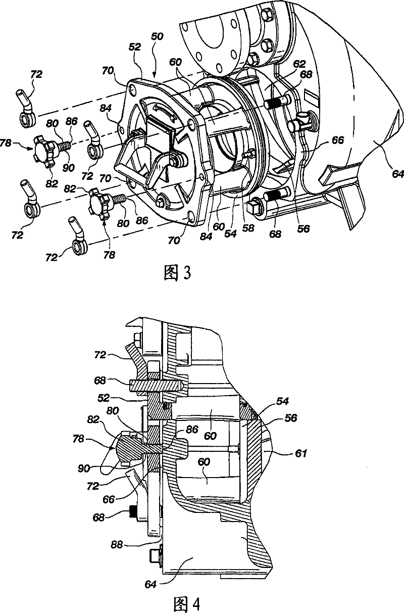
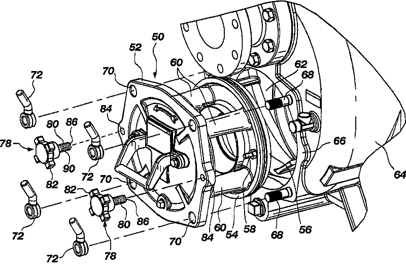
Therefore, adjusting the wear plate is relatively difficult and time consuming, and including the few elements of the adjustment mechanism adds to the cost of the pump

Method used


Image

  • Eccentric pump with clean-out assembly
  • Eccentric pump with clean-out assembly
  • Eccentric pump with clean-out assembly

Examples


Embodiment Construction

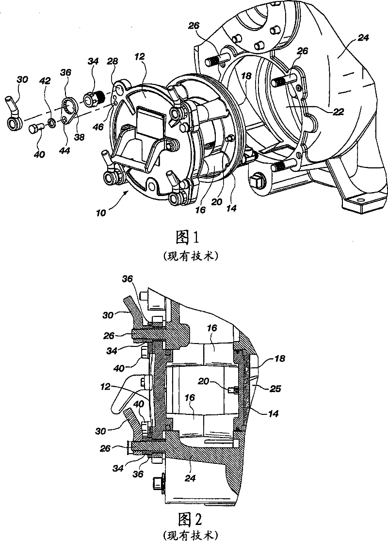
[0021] A prior art purge assembly 10 is shown by comparison in FIGS. 1 and 2 and generally includes an end cap 12 and a support ring 14 , wherein the support ring 14 is spaced from the end cap 12 by a plurality of struts 16 . The support ring 14 provides means for attaching thereto a wear plate 18 which is attached to the support ring 14 by screws 20 . Scavenger assembly 10 fits into opening 22 formed in pump housing 24 so that wear plate 18 is positioned adjacent impeller 25, as shown in FIG. 2 .

[0022] In the prior art pump shown in FIG. 1 , the purge assembly 10 is attached to the pump housing 24 by a plurality of stud bolts 26 which extend through holes 28 formed in the end cover 12 . End cap 12 is held in place by hand nut 30 tightened over stud 26 .

[0023] The means for adjusting the axial position of the wear plate 18 relative to the impeller are also connected with the means for connecting the end cover 12 to the pump casing 24 . In particular, a threaded adjustm...


PUM


Abstract

The present invention provides a clean out assembly for a centrifugal pump, particularly, for example, a self-priming-type of centrifugal pump, is structured to provide easy adjustment of the clean out assembly and axial movement of a wear plate in proximity to the impeller of the pump without the need for tools to effect such movement of the wear plate and clean out assembly.

Description

[0001] Cross References to Related Applications [0002] This application is a non-provisional application claiming priority to Provisional Patent Application Serial No. 60 / 707,006, filed August 10,2005. technical field [0003] The present invention relates to a self-priming centrifugal pump, and more particularly to a purge assembly for a self-priming pump that facilitates access to the interior of the pump and facilitates axial adjustment of the wear plate relative to the impeller. Background technique [0004] Self-priming centrifugal pumps are well known and are often used in industries where fluids with laden solids need to be handled. Self-priming pumps, also known as trash removal pumps, are characterized by a housing in which there are a suction chamber and a separation chamber, which are separated by a wall or a booster chamber. Inside the volute of the pump is an impeller which receives fluid from the suction chamber and centrifugally feeds the fluid into the se...

Claims


Application Information

Patent Timeline
Patent Type & Authority Patents(China)
IPC IPC(8): F04D29/40
Inventor K·M·阿诺德
Owner ENVIROTECH PUMPSYSTEMS INC
Learn More