Unlock instant, AI-driven research and patent intelligence for your innovation.

Debugging method, system and distributed device for target single board

A distributed equipment and single-board technology, applied in transmission systems, digital transmission systems, electrical components, etc., can solve the problems of increased equipment manufacturing costs and hardware maintenance costs, inconvenient debugging environment construction, and high costs

Active Publication Date: 2010-10-27
NEW H3C TECH CO LTD
View PDF3 Cites 0 Cited by
  • Summary
  • Abstract
  • Description
  • Claims
  • Application Information

AI Technical Summary

Problems solved by technology

[0004] However, due to the large number of service boards under the distributed architecture, the solution of adding a debugging interface to hardware on each single board will greatly increase equipment manufacturing costs and hardware maintenance costs
Moreover, when debugging multiple service boards, each service board needs to be connected to the debugging host through a connecting cable (such as a network cable), and a large number of connecting cables crossing together can easily make the connection of one of the single boards unreliable.
In addition, since the single board is generally located inside the device, when setting up the debugging environment, the debugging personnel need to introduce the connecting wires into the inside of the single board, which will bring great inconvenience to the construction of the debugging environment
In short, the debugging scheme under the existing distributed architecture not only has high cost, but also has poor reliability and convenience

Method used


Image

  • Debugging method, system and distributed device for target single board
  • Debugging method, system and distributed device for target single board
  • Debugging method, system and distributed device for target single board

Examples


Embodiment 1

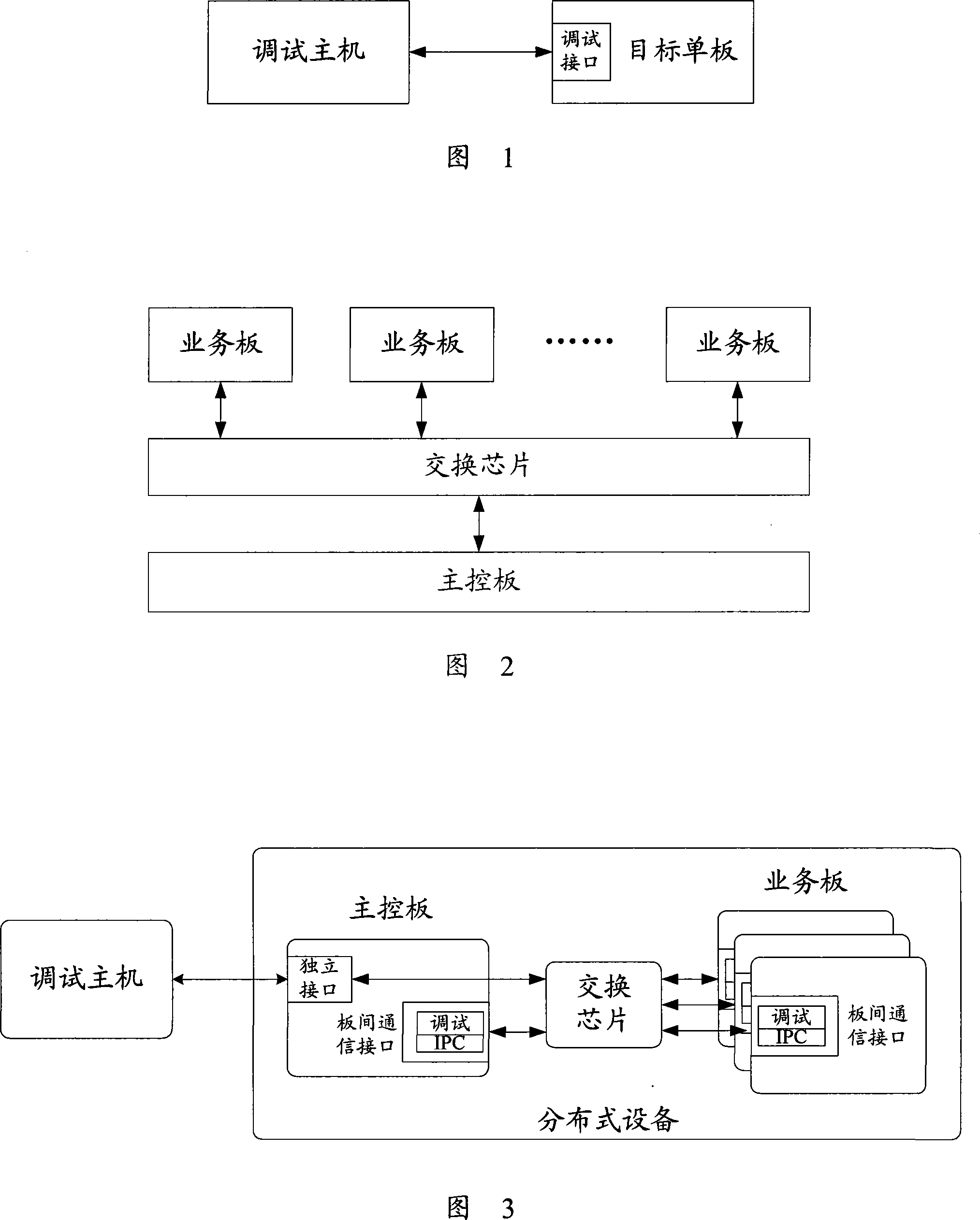
[0071] see image 3 The structure diagram of the debugging system shown includes the debugging host and distributed equipment. Among them, both the main control board and the service board of the distributed equipment have an inter-board communication interface connected to the switch chip, and there is an independent interface on the main control board, which is directly connected to the switch chip, and the debugging host passes the The independent interface is interconnected with each target single board in the distributed equipment.

[0072]In this embodiment, in order to realize debugging, a virtual debugging interface is virtualized on the inter-board communication interface of each single board (including the main control board and the service board). The virtual debugging interface of the board is used to debug the target single board. In addition, in order to ensure normal IPC communication, a virtual IPC interface can be further virtualized on the inter-board commu...

Embodiment 2

[0088] see Figure 6 The structure diagram of the debugging system shown includes the debugging host and distributed equipment. Wherein, there is a service / management interface on the main control board, and the debugging host is interconnected with the target single board in the distributed equipment through the service / management interface.

[0089] In this embodiment, a virtual debugging interface is virtualized on the inter-board communication interface of the service board; a virtual debugging interface is virtualized on the service / management interface of the main control board, and a virtual debugging interface is virtualized on the inter-board communication interface of the main control board. A virtual Ethernet layer-3 interface. The debugging host debugs the target single board through the service / management interface of the main control board and the virtual debugging interface of the debugged target single board, wherein the target single board includes a main con...

Embodiment 3

[0106] see Figure 9 The schematic structural diagram of the debugging system shown includes a debugging host and distributed equipment, wherein there is a service / management interface on the main control board, and the debugging host is interconnected with each target single board in the distributed equipment through the service / management interface.

[0107] In this embodiment, a virtual debugging interface is virtualized on the inter-board communication interface of the service board; a virtual Layer 2 switching unit is set inside the main control board, and the virtual debugging interface is registered on the virtual Layer 2 switching unit, and the virtual Layer 2 switching The physical interface of the unit consists of the service / management interface of the main control board and the communication interface between the boards. The debugging host debugs the target single board through the service / management interface of the main control board and the virtual debugging int...


PUM


Abstract

The invention provides a method for debugging an object veneer, which comprises the steps that: a virtual debugging interface is arranged on the object veneer and a debugging host debugs the object veneer by the virtual debugging interface of the object veneer. Besides, the invention also provides a debugging system and a distributed equipment of an object veneer. By utilizing the technical proposal provided by the invention, debugging cost can be lowered and the reliability and convenience of debugging can be promoted.

Description

technical field [0001] The invention relates to debugging technology in a communication system, in particular to a target single board debugging method, system and distributed equipment. Background technique [0002] Debugging is an essential step in the development of network equipment and its subsequent maintenance. figure 1 A schematic diagram of the debugging structure of an independent single board is shown, and the debugging host and the target single board are connected and communicated through a debugging interface (such as a network port), so as to realize the debugging function of the target single board. [0003] With the rapid development of Internet technology, people have higher and higher requirements for equipment processing performance. In order to meet this demand, most equipment adopts a distributed architecture. figure 2 It shows a schematic structural diagram of a distributed device, including a main control board and multiple service boards, and the m...

Claims


Application Information

Patent Timeline
Patent Type & Authority Patents(China)
IPC IPC(8): H04L12/24H04L12/26H04L12/56H04L12/931
Inventor 赵汉表
Owner NEW H3C TECH CO LTD