
Method for operating a vibrating gyroscope and sensor system

A vibrating gyroscope and sensor technology, applied in gyroscope/steering sensing equipment, instruments, gyro effect for speed measurement, etc., can solve problems such as delay in vibration characteristics

Inactive Publication Date: 2008-09-10
VDO AUTOMOTIVE
View PDF2 Cites 5 Cited by
  • Summary
  • Abstract
  • Description
  • Claims
  • Application Information

AI Technical Summary

Problems solved by technology

However, this is delayed by the start-up characteristics of the control circuit (transient response Einschwingverhalten)

Method used


Image

  • Method for operating a vibrating gyroscope and sensor system
  • Method for operating a vibrating gyroscope and sensor system

Examples


Embodiment Construction

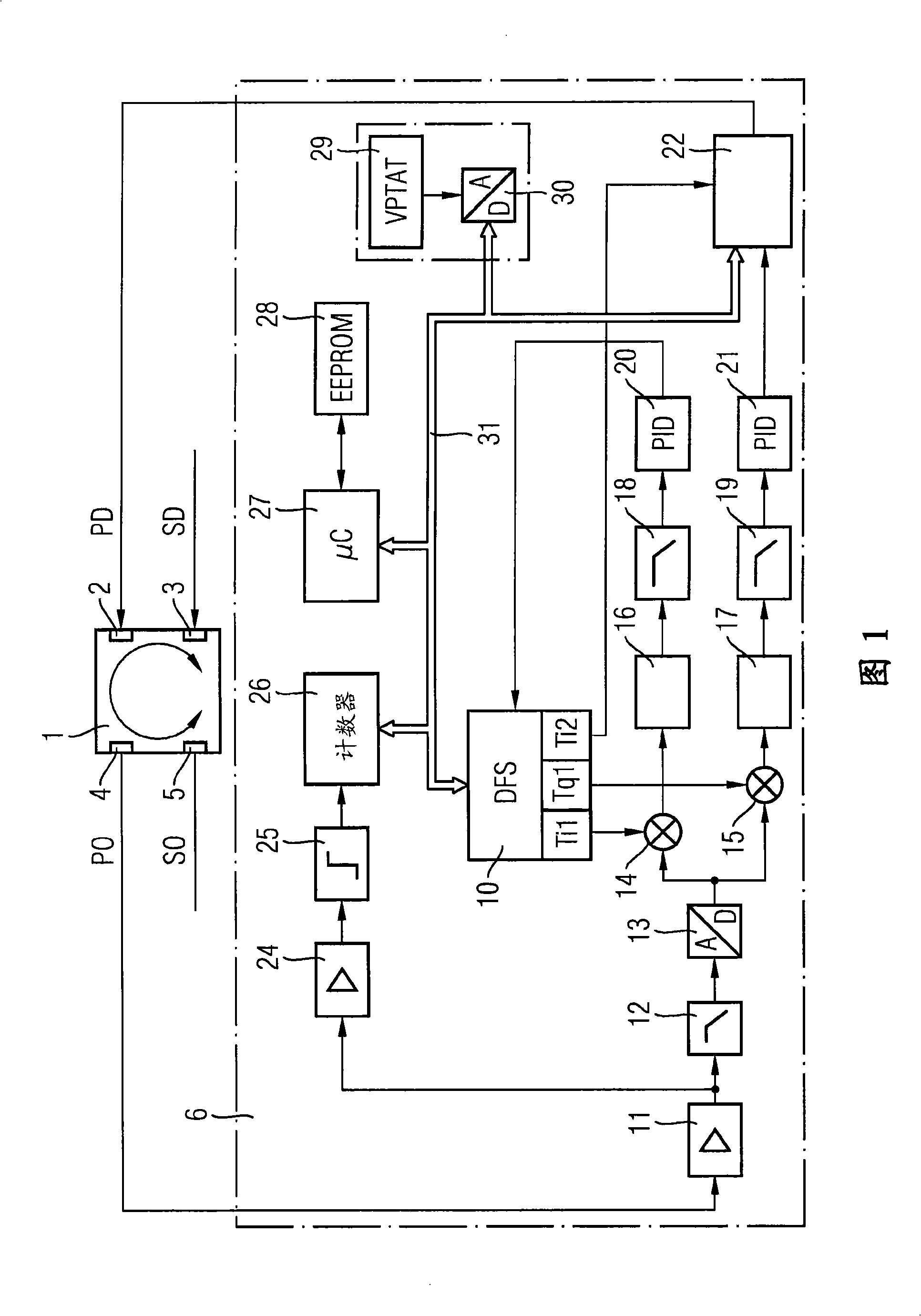
[0018] The sensor system and its components are represented as block diagrams though. However, this does not mean that the sensor system according to the invention is restricted to being realized by means of individual circuits corresponding to the blocks. Instead, according to the invention, the sensor system is realized in a particularly preferred manner by means of highly integrated circuits. A microprocessor may be used here, which, when suitably programmed, performs the processing steps shown in the block diagram.

[0019] FIG. 1 shows a block diagram of a sensor system with a vibrating gyroscope 1 having two inputs 2 , 3 for a primary excitation signal PD and a secondary excitation signal SD. Excitation takes place via suitable transducers (eg electromagnetic transducers). The vibrating gyroscope also has two outputs 4 , 5 for the primary output signal PO and the secondary output signal SO. These signals reflect individual vibrations at spatially offset locations on t...


PUM


Abstract

The invention relates to a method for operating a vibrating gyroscope and to a sensor arrangement comprising such a vibrating gyroscope. Said vibrating gyroscope is used as a resonator and is part of at least one control circuit that excites the vibration gyroscope by feeding an excitation signal with its natural frequency. An output signal can be tapped from the vibrating gyroscope from which the excitation signal can be derived by filtering and amplification. The invention is characterized in that, once the sensor arrangement is switched on, the frequency of the excitation signal is adjusted by exciting the vibrating gyroscope, before the excitation signal is fed, to oscillate freely, measuring the frequency of the free oscillation and feeding the excitation signal to the vibrating gyroscope with the measured frequency.

Description

technical field [0001] The invention relates to a method for operating a vibrating gyroscope and a sensor system with a vibrating gyroscope which constitutes a resonator and is part of at least one control circuit which, by inputting an excitation signal, vibrates the gyroscope The vibrating gyroscope is excited by the natural frequency of the gyroscope, wherein the output signal is obtained from the vibrating gyroscope, and the excitation signal is derived from the output signal by filtering and amplifying. Background technique [0002] For example, a rotation rate sensor is disclosed in EP 0 461 761 B1, in which the vibration gyroscope is excited in two axes directed radially with respect to the main axis, for this purpose on the vibration gyroscope Primary and secondary control circuits with corresponding converters are provided. If such a rate-of-rotation sensor in a motor vehicle is to be used to stabilize the movement of the motor vehicle, the rate-of-rotation sensor ...

Claims


Application Information

Patent Timeline
Patent Type & Authority Applications(China)
IPC IPC(8): G01C19/56G01C25/00G01C19/5649
CPCG01C19/5649G01C19/00G01C19/56G01C25/00
Inventor 拉斐尔·迈尔-韦格林海因茨-维尔纳·莫雷尔
Owner VDO AUTOMOTIVE
Learn More