Fastening device

A technology for fastening devices and threaded parts, which is applied in the direction of threaded fasteners, locking fasteners, thin plate connections, etc., can solve the problems of increasing and reducing bolt types, hindering costs, etc., and achieve the effect of cost reduction

Inactive Publication Date: 2008-09-17
AOYAMA SEISAKUSHO CO LTD
View PDF3 Cites 14 Cited by
  • Summary
  • Abstract
  • Description
  • Claims
  • Application Information

AI Technical Summary

Problems solved by technology

This increases the variety of bolts and hinders cost reduction

Method used


Image

  • Fastening device
  • Fastening device
  • Fastening device

Examples


no. 1 example

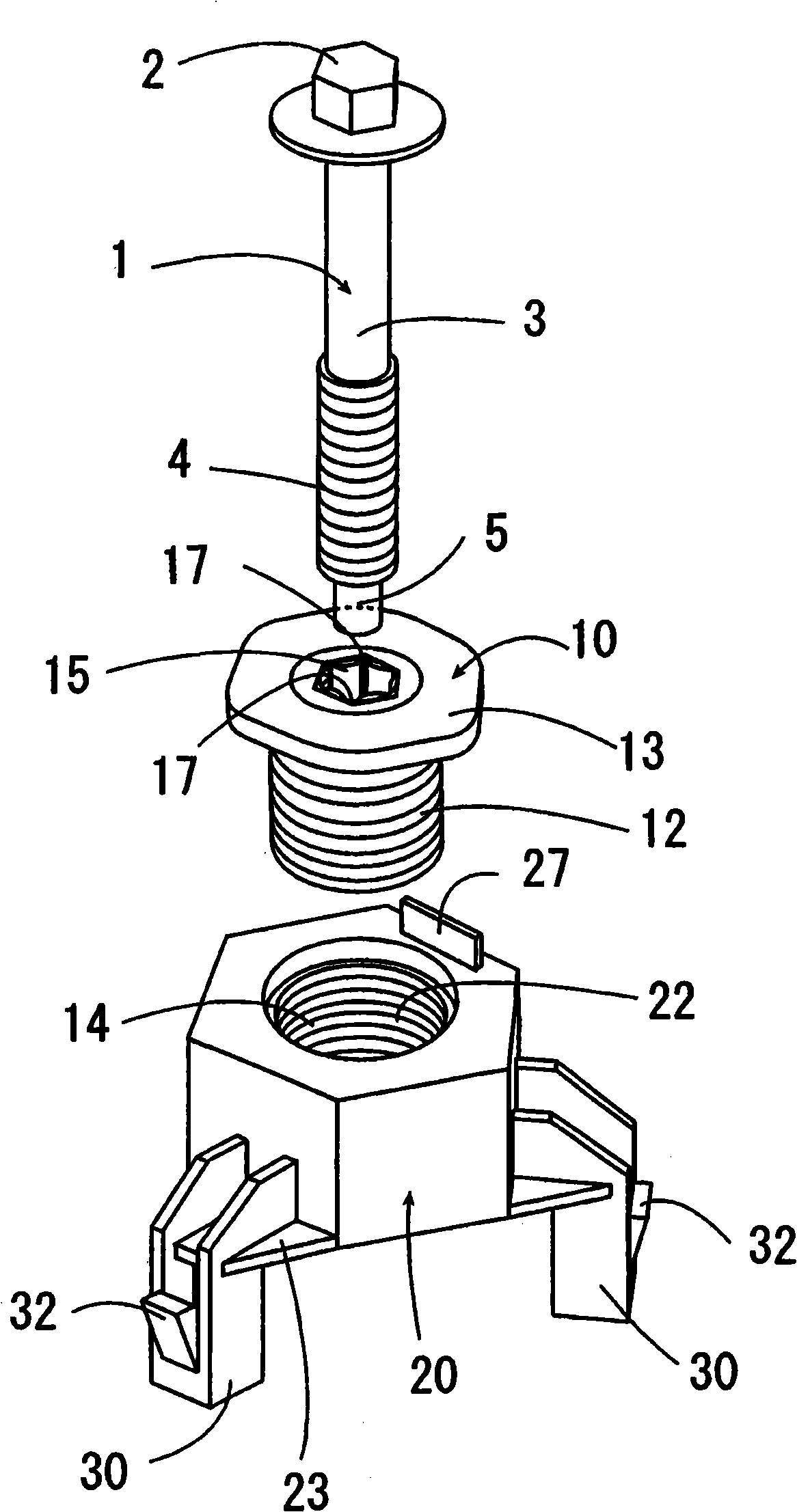
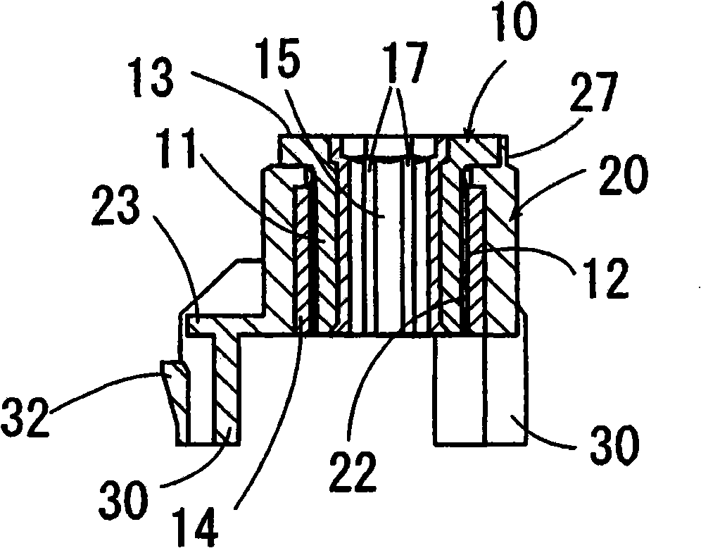
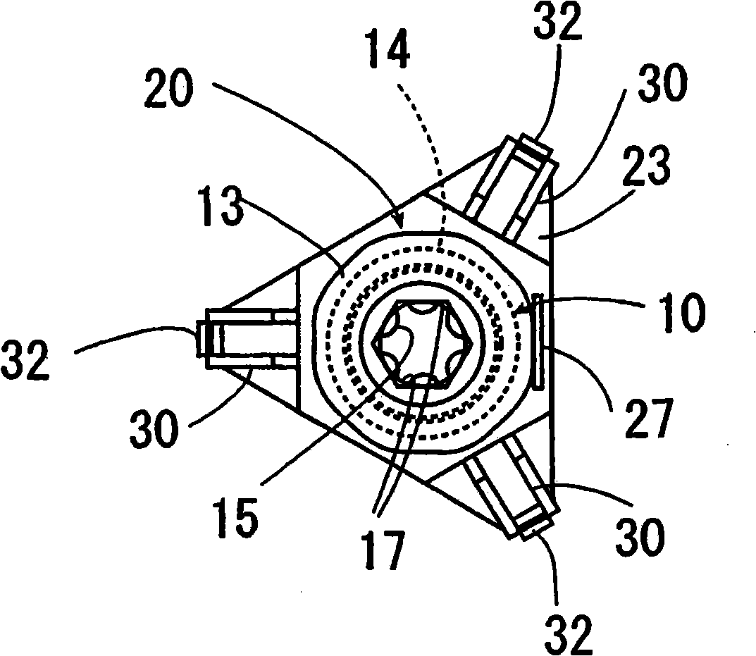
[0029] Figures 1 to 10 The first embodiment of the present invention is shown separately. The fastening device of this embodiment includes a metal bolt 1 , a metal movable spacer 10 , a sleeve 20 , and a metal nut 31 . The first member 40 is formed with a bolt insertion hole 42 and the metal nut 31 is welded to the rear surface of the first member 40 . The bolt 1 includes a head portion 2 , a cylindrical shaft portion 3 , and a positively threaded male thread portion 4 formed on the tip side of the cylindrical shaft portion 3 . The bolt 1 is screwed into the movable spacer 10 as described below. A rod top 5 whose diameter is smaller than the root diameter of the male thread portion 4 is formed on the tip side of the male thread portion 4 for easier insertion and screwing into the female thread portion of the movable spacer 10 and nut 31 .

[0030] The sleeve 20 is fixed to the surface of the bolt insertion hole 42 of the first member 40 . The sleeve 20 integrally encapsul...

no. 2 example

[0044] In the first embodiment as described above, the movable spacer 10 and the sleeve 20 are screwed to each other in a state where the movable spacer 10 is housed in the sleeve 20 . exist Figure 11 In the shown second embodiment, the diameter of the movable spacer 10 is formed larger than the diameter of the sleeve 20, so the movable spacer 10 and the sleeve 20 are in the state where the sleeve 20 is housed in the movable spacer 10 Tighten each other.

[0045] The movable spacer 20 includes a cylindrical portion 11 , and a plate-shaped portion 13 provided to close an opening portion on one side of the cylindrical portion 11 . A negatively threaded female thread portion 16 is formed on the inner peripheral surface of the cylindrical portion 11 . The elastomer layer 15 is formed on the inner peripheral surface of the center hole drilled in the plate-like portion 13 . Like the first embodiment, the elastomer layer 15 is made of synthetic resin or synthetic rubber such as e...


PUM


Abstract

A fastening device, including: a sleeve 20 fixed to a first member 40; a bolt 1; and a movable spacer 10 that is engaged with a male screw portion 4 of the bolt 1 to be detachable upon receiving a transmission torque exceeding a predetermined value, and moves to a position coming into contact with a second member 50 distanced from the first member 40 as a result of rotating while mating with the reversal screw portion 22 of the sleeve 20 upon receiving the rotational torque from the bolt 1. On the inner peripheral surface of the movable spacer 10, an elastic body layer 15 which elastically deforms when engaged with the male screw portion 4 of the bolt 1 to exhibit a torque transmitting function and a pitch deviation absorbing function is formed.

Description

technical field [0001] The invention relates to a fastening device for securing two separate components and keeping them separated by a common distance. Background technique [0002] Conventionally, fastening devices for fixing two separate members to each other and keeping them separated by a shared distance have been proposed in the technical field of automobiles and the like. For example, the following patent documents 1, 2 and 3 respectively disclose a fastening device comprising a sleeve fixed to a first member of one of two separate members by welding, and screwed into a movable spacer of the sleeve by reverse screwing. and a bolt with a male thread portion that can cooperate with a female thread portion formed on the movable spacer is formed on the top end of the shaft portion. The male threaded portion of the bolt cooperates with the movable spacer in such a way that it is detachable from each other when a transmitted torque in excess of a predetermined value acts o...

Claims


Application Information

Patent Timeline
Patent Type & Authority Applications(China)
IPC IPC(8): F16B5/02F16B33/02F16B37/04F16B39/22
CPCF16B5/0283Y10T403/75
Inventor 伊藤修二长谷川祯辰
Owner AOYAMA SEISAKUSHO CO LTD
Why Eureka
Try Eureka